Download
1 / 26
260 likes | 467 Vues
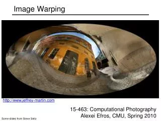
CS 563 Advanced Topics in Computer Graphics View Interpolation and Image Warping. by Brad Goodwin. Images in this presentation are used WITHOUT permission . Over View. General Imaged-Based Rendering Interpolation Plenoptic Function Layered Depth Image (LDI) . Introduction.

E N D
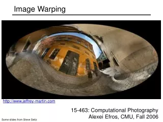
CS 563 Advanced Topics in Computer GraphicsView Interpolation and Image Warping by Brad Goodwin Images in this presentation are used WITHOUT permission
Over View • General Imaged-Based Rendering • Interpolation • Plenoptic Function • Layered Depth Image (LDI)
Introduction • Image Based Rendering (IBR) • Composed of photometric observations • Mix of fields (photogrammetry, vision, graphics) • Texture mapping • Environment mapping • Realistic surface models • Uses from virtual reality to video games • Just render the 3D scene? • Judge results? • Different types of rendering using different amounts of geometry
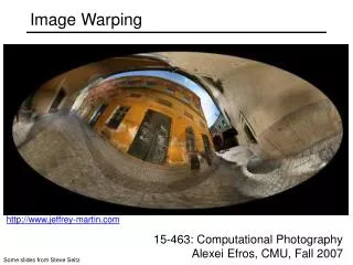
Interpolation • Morphing • interpolating texture map and shape • Generation of a new image is independent of scene complexity • Morph adjacent images to view between • based on viewpoints being closely spaced • Uses camera position, orientation and range to deteremine pixel by pixel • Images pre computed and stored as morph maps
About this method • Method can be applied to natural images • Only synthetic were tested with this paper • Of course this paper was in ’93 so hopefully someone’s tested them by now • Only accurately supports view independent shading • Others could be used on maps but they are discussed
Types of Images • Can be done with natural or sythetic images • Sythetic • easy to get the range and camera data • Natural • Use ranging camera • Computed by photogrammetry or artist
General Setup • Morphing can interpolate different parameters • Camera position • Viewing angle • Direction of view • Hierarchical object transformation • Find correspondence of images • Images arranged in graph structure
Find correspondence • Usually done by animator • This method • Form of forward mapping • uses camera and range to do it • Cross dissolving pixels(not view-independent) • Done for each source image • Quadtree compression • Move groups of pixels • Scene moves opposite camera • Offset vectors for each pixel (“morph map”) • Small change more accurate when interpolated
Offset vectors Sampled every 20 pixels
Overlaps and holes • Overlaps • Local image contraction - several samples move to the same pixel in interpolated image • Perpendicular to oblique • Holes • Show when mapping source to destination • Background color • Interpolate four corners of the pixel instead of center (filling and filtering) • Interpolate adjacent offset vectors • Or if part seen in interpolated but not source
Block Compression • Pixels ten to move together so block compression algorithm is used to compress morph map. • Related to image depth complexity • High complexity low compression ratio
View independent Priority • Established to determine points that are viewable • Pixels are ordered from back to front based on Z-coordinates established in morph map • Eliminates need for interpolating the Z-coordinates of every pixel and updating the Z-buffer in the interpolation process.
Applications • Virtual Reality • Motion blur • Uses super-sampling of many images computationally which is expensive thus inefficient • Reduce cost of computing a shadow map • Only for point light sources • Create 3D primitives without creating 3D primitives
Plenoptic Modeling • The Plenoptic function • Latin root plenus – complete or full optic - pertaining to vision • Parameterized function for describing everything that is visible from a given point in space • Used as a taxonomy to evaluate low-level vision • Adelson and Bergen postulate “…all the basic visual measurements can be considered to characterize local change along one or tow dimensions of a single function that describes the sructure of the information in the light impinging on an observer.”
Parameters azimuth and elevation angle
Plenoptic • Set of all possible environment maps for a given scene • Specify point and range for some constant t • A complete sample can be defined as a full spherical map
Plenoptic Modeling • Claimed that all image-based rendering approaches are just attempts to create a plenoptic function with just a sampling of it • Set up is the same as most approaches • Set of reference images which are warped to create instances of the scene from arbitrary view points
Sample Representation • Unit sphere • Hard to store on a computer • Example of all distorted maps • Six planar projections of a cube • Easy to store • 90 degree face requires expensive lens system to avoid distortion • Oversampling in corners • Have to choose Cylindrical • Easily unrolled • Finite height :problems with boundary conditions • No end caps
Aquiring Cylindrical Projections • Get the projections is simple • Tripod that can continuously pan • Ideally camera’s panning motion should be exact center of tripod • When panning objects are far away slight misalignment is tolerated • Panning takes place entirely on the x-z plane • Both images should have points within each other.
Find the projection of the output camera on input cameras image plane • That is the intersection of the line joining the two camera locations with the input camera’s image plane • Line joining the two cameras is the epipolar line • Intersection with the image plane is the epipolar point
Map image point to output cylinder • Same techique for comparing points used with face mapping from last week
Layered Depth Images • Paper presents some methods to render multiple frames per second on a PC • Sprites – are texture maps or images with alphas (transparent pixels) rendered onto planar surfaces • One method warps Sprits with Depth • Warps depth values and uses this information to add parallax correction to a standard sprite renderer • LDI • Single input camera • Contains multiple pixels along each line of sight • Size of representation grows linearly with the depth complexity of the scene • Uses McMillan’s warp odering algorithm because data is represented in a single image coordinate system.
References • Chen S E and Williams L, "View Interpolation for Image Synthesis", Proc. ACM SIGGRAPH '93 McMillan L, and Bishop, "Plenoptic Modeling: An Image-based Rendering System", Proc. ACM SIGGRAPH '95 • Shade, Gortler, He and Szeliski, "Layered-Depth Images", Proc. ACM SIGGRAPH '98 • McMillan L. and Gortler S,"Applications of Computer Vision to Computer Graphics: Image-Based Rendering - A New Interface Between Computer Vision and Computer Graphics, ACM SIGGRAPH Computer Graphics Newsletter, vol 33, No. 4, November 1999 • Shum, Heung-Yeung and Kang, Sing Bing, A Review of Image-based Rendering Techniques, Microsoft Research • Watt, 3D Graphics 2000, Image-based rendering and phto-modeling (Ch 16) • http://www.widearea.co.uk/designer/anti.html • http://www.dai.ed.ac.uk/CVonline/LOCAL_COPIES/EPSRC_SSAZ/node18.html • http://www.cs.northwestern.edu/~watsonb/school/teaching/395.2/presentations/14