Advanced Control Systems for Plasma Technology: Microprocessors, DSPs, and Real-Time Applications
This paper presents a comprehensive analysis of microprocessors, microcontrollers, and digital signal processors (DSPs) within the context of advanced control systems, particularly in the plasma technology domain. It discusses the challenges posed by harsh environments, such as cosmic rays and neutron fluency, impacting high-tech devices. Real-time control, sensor integration, and the complexities of plasma parameters require sophisticated control strategies. The paper elaborates on PID controllers and data acquisition systems, emphasizing their importance in ensuring accurate and efficient plasma control.

Advanced Control Systems for Plasma Technology: Microprocessors, DSPs, and Real-Time Applications
E N D
Presentation Transcript
Embedded control European PhD – 2009 Microprocessors, microcontrollers and DSP´s Horácio Fernandes
Microprocessors, microcontrollers and DSP´s • Container for a number of commonly used sub-units • ALU • DMA • RAM • I/O
“Obsolete” devices • Due to high degree of integration, some high-tech devices can NOT be used on harsh environments • Space (cosmic rays) • High neutron fluency • Radioactive (gamma rays) • “Bit” errors • Doping contaminants
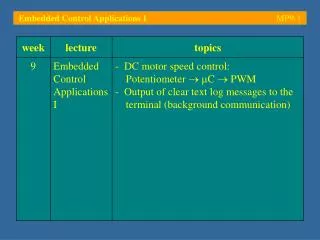
Real-time systems • Definition of real-time • Definition of Human time scale • Real-time control and controllers
Controller #1(PID) Sensor(Magnetics) Actuator (PSU) Sensor(Magnetics) WaveformGenerator #1 Tokamak Actuator (Power Suplies) DATAACQUISITIONSYSTEM Sensor(Pressure/Interferometry) Tokamak: Actuator (Gas Puffing) Controller #2(PID) Actuator (Gas Puffing) Actuator Y Sensor X Controller #(PID) Sensor(Interferometry) WaveformGenerator #2 The control system • “Trial-and-error” type operation • Hard to get similar discharges, as the plasma is a multivariable complex system • Reprogram of waveforms is normally an empiric and lengthy task • Data acquired needs to be correlated manually against control waveforms • Single-Input Single-Output (SISO) ANALOG controllers • Not easily Re-configurable • Hard to Optimize • Allows only simple control schemes (e.g PID) • Control of Plasma Parameters are NOT coupled!
Sensors Actuators Control Unit System Components Symposium on Plasma Physics and Technology
Processing unit • 8 Analog channels • Galvanic isolated • 2 MSample/s • 14-bit • 512 MB SDRAM • DSP • FPGA • HS Serial connections • PCI bus
EP2 VS Shape & Current Control (PPCC) PF Coils Magnetics VUV impurities GAS + Pellets Interferom/Polarim Vis Da, Brem, ELM NBI Neutron X-ray etc. Vis H/D/T plasma ICRH ECE Te (R) Confinement q profile LHCD CXS Ti (R) Flux surfaces EQX TAE / EFCC LIDAR Ne&Te(R) Wall Load MSE pitch (R) EQX kinetic map Simulink code Coil Protection X-ray Ti (0) R-T Controller Rob Felton - RTMC Workshop R-T Signal Server Comms network ATM, some analogue Sensors & actuators @ JET
Computer Architectures • Harvard architecture (/von Neumann) • RISC(PIC, IBM Power PC) / CISC (80x86) • Clocking, instruction pipelining, 14 bit instruction set
PIC architecture • Single chip: • CPU • Memory • RAM • PROM/ EEPROM • oscillator • timers • watchdog • I/O • Digital • ADCs • Communications
PICs • Code efficiency - 8 bit /Harvard • Conventional Microcontrollers -1 internal bus (Z80) • Safety coding • 12, 14 or 24 bit “program memory word” • Jumps to data area impossible • Instruction Set • 33 instruction (MID range) • Single instruction cycle (=4 clock cycles); /CALL, GOTO, bit test (BTFSS, INCFSZ) • Speed (2x 386 SX 33MHz)
PICs (cont.) • Static Operation – registers are kept valid during STOP (Sleep – 1uA sink current) • Current driver • I/O pin: sink 25mA or 100mA (total) • LEDs and triacs • Several series options • Speed, thermal • Casing (sizes) • I/O, timers, serial comms, A/D • memory
DSP • 40 bit ALU • 2x40 bit accumulators • 1x40 bit bidirectional shifter • Barrel shift -15 bits right, 16 bits left • Integers vs float
Terminology • Microcontroller (sw relevancy) • I/O (external world) • Software (information) • Bugs • Programming language (ASM, C) • Hardware • Microprocessor • Memory • Interface and signal conditional circuits • Power supply (digital, analog and programming ground and shielding)
CPU Data Memory Program Memory DSP Engine Interrupts I/O Ports Timers Input Capture Module Output Compare Module Quadrature Encoder Interface (QEI) 10-bit A/D Converter 12-bit A/D Converter UART Module SPITM Module I2CTM Module Data Converter Interface (DCI) Module CAN Module dsPIC30F
Harvard • Independent Buses • Instructions are bigger than1 byte (Program memory) • Program memory: • Optimized • Single word instruction per cycle • In one jump an instruction is always executed • /von Neuman instructions with several bytes
Harvard Architecture • pipeline • 2 stages instruction execution • fetch and execution in a single cycle • Each instruction is autonomous • Every data included • No more program data access • 4 clock per instruction cycle
Instruction format • Word or byte-oriented • Bit-oriented • Literal • DSP operations • Control operations • OpCode • Variable number of bits • 2^6=64 (app. 35 instructions)
Instruction format dsPIC30F Mid-range PICs (14 bit)
Memory organization • Registers and static memory • Work register • Mid->dsPIC • File registers~RAM • General Purpose Registers (GPRs) • Special Function Registers (SPRs) • Memory banks • Limitation due to adress bits • Selection bits (avaiable trough STATUS)
Special Function Registers • Base Architecture • Reserved names • INTCON, TMR0, STATUS • R/W and read only • Some registers do not exist physically • Some registers are copied among bank memory • STATUS, FSR, INDF • Including GPR (0x70 a 0x7F) • PORTB (Banks 0 e 2) • Power ON/Reset
General Purpose Registers • User defined • Wide implementation • Indirect adress • pointers • Easy incrementation or decrementation • INDF (0x00) provide adress copy of FSR • ie changing INDF data at that adress is changed INDF(=*FSR) • de-referencing • Address: 100 102 104 106 • Variable: i j k ptr • Content: 3 5 -1 102 • int i, j, k; • int *ptr;
Example • STATUS
Interruptions and I/O • Communication between microcontroller and external world • Multi-functional digital output • Communication protocol • ADCs e DACs • Events monitoring
I/O - Port • TRISx: Data Direction register • PORTx: I/O Port register • LATx: I/O Latch register • C options in TRISx • Quick & simple • Slow & secure
Change Notification (CN) Pins • Weak pull-up (current source) • Avoiding external resistores • Originate interruptions • Change in pin states • 24 pins avaiable
Interruptions • vs Polling (attention) • Quick response to events • Peripherics • Driven actions • After taken action continues previous process • Maskable/non-maskable • Variable saving (PC e Stack) • Quick execution
INT Pin Interrupt (external interrupt) TMR0 Overflow Interrupt PORTB Change Interrupt Comparator Change Interrupt Parallel Slave Port Interrupt USART Interrupts Receive and Transmit Interrupt (CAN) A/D Conversion Complete Interrupt LVD Interrupt Data EEPROM Write Complete Interrupt Timer Overflow Interrupt CCP Interrupt SSP Interrupt Interruptions (cont.)
Communications • Serial • Synchronous • I2C • SPI • Asynchronous • RS232, RS485, RS422 (RS232 differential) • Point to point • Point/multi-point • USB, SSP • CAN • Parallel
Serial Communications • Start bits - Always 1 bit • Stop bits – 1, 1.5 ou 2 bits • Data bits - 7 ou 8 bits • Parity bits • none - no error detection • odd or even - error detection required • 1 bit added to give bit summing odd or even • CheckSum: redundancy check • CRC (cyclic redundancy check)
HandShaking • Data Terminal Ready • Data Set Ready • Clear to Send • Request To Send • Transmit Data • Receive Data • Ring • Data Carriage Detected • Ground RTS Data Terminal Equipment - Data Comunication Equipment
USART/UART • Universal Synchronous/Asynchronous Receiver Transmiter • Shift register • SYN (0b01000010)
I2C • Two bidirectional “open-drain lines” • Serial Data (SDA) • Clock (SCL) • “Pull-up” – resistor ~k • Multi-master • Master node — clock controller • Slave node — all others
I2C • 7-bit address space (10-bit addressing) • 16 reserved addresses (max 112 nodes) • Vel. • Normal - 100 kbit/s (standard mode) • Low-speed mode - 10 kbit/s (até DC) • Fast - 400 kbit/s (Fast mode) or 1 Mbit/s (Fast mode plus or Fm+), 3.4 Mbit/s High Speed mode • Max. bus capacity - 400 pF.
SPI • Operation modes • 8-bit and 16-bit Data Transmission/Reception • Master e Slave • Framed SPI Modes • Operation: 8-bit vs. 16-bit
SPI • Ideal for single-master/single-slave • Single-master bus • Do not have slave acknowledgment ! • Full duplex • 1-10Mbit • Dual-Shift register
Oscillator • Oscillator modes ( default clock source) • EC External Clock • ECIO External Clock with IO pin enabled • LP Low Frequency (Power) Crystal • XT Crystal/Resonator • HS High Speed Crystal/Resonator • RC External Resistor/Capacitor • RCIO External Resistor/Capacitor with IO pin enabled • HS4 High Speed Crystal/Resonator with 4x frequency PLL multiplier enabled
Inverter gain (mode) Frequency (power) Crystal (precision) Wake-up (frequency, noise, sleep wake-up) Oscillator Modes
PLL • Advantages PLL • EMI • SW program. • Structure • VCO • Divider • Comparator
Timers (dsPIC) • Timer 1