Download
1 / 34
370 likes | 946 Vues
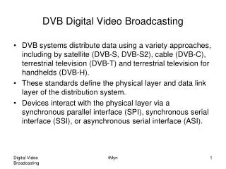
Advantages of Digital Broadcasting. Better signal to noise ratio Reduced interference Possible single frequency networks Less multipath distortion Automatic tuning Auxiliary data services. DRM - Digital Radio Mondiale.

E N D
Advantages of Digital Broadcasting • Better signal to noise ratio • Reduced interference • Possible single frequency networks • Less multipath distortion • Automatic tuning • Auxiliary data services
DRM - Digital Radio Mondiale • Developed by a group including broadcasters, transmitter and receiver manufacturers, research labs, universities, and government agencies. • Designed to eventually replace AM in the present AM bands (0.15 to 30 MHz). • Transmitted bandwidth typically 9 kHz. Standard covers 4.5 to 20 kHz. • Complete specifications documented with ETSI and ISO. Consumer receivers just starting production. • Different configurations for local and shortwave conditions.
Processing of Signals • A/D conversion • Audio processing • Source coding - MPEG AAC • Forward error correct-ion (FEC) coding • OFDM (Orthogonal frequency division multiplex) • Channel coding - time +frequency interleave • Digital modulation of subcarriers • Inverse Fast Fourier Transform (IFFT) • Interpolation • RF frequency generation and modulation in DDS (direct digital synthesizer) • Upconversion • Power amplification
Audio Processing The minimum amount of control is automatic peak limiting, that is, reducing the amplification whenever the input level is so high that overload and clipping will be produced in later steps. Audio levels in program material vary with the source (live microphone, taped, satellite, CD’s etc and with the skill and attention level of the operator. It is desirable to have some automatic control of audio levels. When most listeners are located in noisy environments such as automobiles, it is good to reduce the dynamic range (ratio of soft to loud sounds) so that soft music or speech will not be lost in the ambient noise.
Source Coding The output bit rates of the A/D converter are much greater than can be transmitted in reasonable broadcast bandwidths. (1536 kbits/second from the A/D converter for one channel. • Fortunately it’s possible to reduce these bit rates drastically with little or no perceptible loss of audio quality. The coding technique for high quality audio signals uses the properties of human sound perception by exploiting the spectral and temporal masking effects of the ear. • MPEG Advanced Audio Coding (AAC) perceptual coding allows great bit rate reduction while maintaining excellent audio quality. CD quality stereo requires only 96 to 128 k bits/s. and good monaural AM 16 to 24 kb/s. It is specified as the source coding method for DRM.
Error Correction Coding Bit errors due to noise, interference from other trans-mitters, and multipath propagation produce audible clicks, squawks, and other noises at the receiver. Forward Error Correction (FEC) coding adds calculated bytes or bits to the signal to make it possible to detect and in many cases correct erroneous bits at the receiver. Similar codes are used to make compact disks (CD’s) and hard disk drives nearly error free in spite of imperfections in the recording medium. Good error correction is a major consideration in the design of these systems. FEC is most effective when error bits are isolated or come in short bursts.
Error Correction Coding (2) • Multipath propagation tends to make the delayed signal interfere with later bits of the desired signal. It can also result in a delayed signal being 180 deg. out of phase and canceling a desired signal. With a multicarrier signal this normally affects one or a few adjacent carriers at a given time. The bits of the data stream are scattered among the carriers so that errors on several adjacent carriers become isolated errors in the reconstituted bit stream.
Orthogonal Frequency Division Multiplex Uses a relatively large number of subcarriers that fill the allocated bandwidth with a low data rate per carrier. Used to minimize multipath problems. DRM Mode A - 24 carriers/kHz = 204 in 9 kHz Mode B (SW) - 21 carriers/kHz = 182 in 9 kHz Modulation of each carrier is QAM 4, 16, or 64 states. Synchronization signals are distributed thru each frame to give the receiver a phase and amplitude reference for each carrier.
History of OFDM • OFDM has been used in radio communication for 50 years. The Collins Kineplex system in the 1950’s put 24 300-baud teletype channels on a single SSB transmitter. The mathematical theory of the system probably dates from the 1930’s. • Implementation of OFDM with analog circuits was very complex. The 24 channel receiver took up nearly all of a 6 foot rack.
Phase and Amplitude Modulation of Subcarriers • Various possibilities • Simplest form is BPSK (binary phase shift keying) • Reference phase = 0 degrees (0 Logical) • Other state = 180 degrees (1 Logical) • 1 bit / Hz
Inverse Fast Fourier Transform • Converts desired frequency spectrum to in-phase and quadrature waveforms • Efficiently executed in DSP (digital signal processor) Interpolation (smoothing) • Output of IFFT is a stepped waveform • Must be smoothed to avoid producing spurious sidebands
Power Amplification Typical peak-to-average power ratio for multi-carrier systems is 10:1 (10 dB) with infrequent higher peaks. DRM requires high power for international broadcasting (25 to 100 kW average power) A linear amplifier will have about 20 % efficiency for this type of signal. For example, 125 kW dc in for 25 kW average power out. A multicarrier signal can be amplified with 75 to 80% efficiency by splitting it into two signals. 1. A constant amplitude RF signal with the phase variations of the desired output signal (including phase reversals). 2. An amplitude (envelope) signal defining the instantaneous amplitude of the desired output.
Power Amplification (2) • The phase modulated signal can be amplified by the class C intermediate and driver amplifiers of a typical local AM or short wave transmitter. • A class C anode modulated amplifier effectively multiplies the phase modulated signal by its anode voltage (the envelope signal), producing the desired output. • The time delay (phase shift) of the phase and amplitude signals must be matched to a fraction of a microsecond . The OFDM signal contains phase reversals (points at which the amplitude goes rapidly to 0 and then increases with reversed phase).
Mathematical analysis shows that though the OFDM I/Q signal is limited to its designated bandwidth with only a small amount of out-of-band energy, the phase and amplitude signals both are wideband. If they are properly matched their out-of-band sidebands cancel. Spectra of signals for amplitude-phase amplification
Transmitter Requirements • The fundamental requirement is that the transmitter function as a linear amplifier and this section shows how linear amplification can be achieved with existing AM broadcast transmitter designs. • As has been described in the previous section, the DRM signal from the OFDM modulator takes the form of a group of equally spaced carriers, with the digital information being modulated onto the carriers in terms of phase and amplitude. • This signal is termed an I/Q signal, as it is complex, and contains In-phase and Quadrature components.
In raising the level of this signal to the power required for broadcast transmission it is imperative that the correct phase and amplitude relationship of the "I" and "Q" components is maintained. In other words, the DRM signal must not be distorted in the power amplification process. • If the signal is distorted, errors will be introduced and the Bit Error Rate (BER) may fall to unacceptable levels and the DRM signal be unusable and/or out-of-band radiation become excessive. To avoid distortion, the power amplifier must therefore have a linear transfer function such that the output signal is an exact replica of the input but at a higher power level.
A factor that has to be borne in mind for a DRM amplifier, is the peak to mean ratio of the DRM signal. The power level of a DRM signal is generally stated in terms of its mean or average value; however the instantaneous peak amplitude of the combined carriers exceeds this value by a large amount. A typical DRM signal has a peak to mean ratio of 10dB, thus an amplifier producing a signal having an average power of 10kW needs a peak power capability of 100kW. • In a practical amplifier, a point is reached where gain compression occurs and the transfer characteristic flattens out. The amplifier must be operated on the linear portion of its characteristic.
It is possible to construct a linear amplifier to provide the power level required for broadcast transmission, but its energy conversion efficiency is very poor, typically 20 – 30%; significant cooling is required and operating costs will be high. • Although some earlier low power transmitters used linear amplifiers, high power AM transmitters invariably use non-linear class C operation to achieve high conversion efficiency. In a valve (electronic tube) transmitter, the grid bias voltage is chosen such that the valve conducts over a limited range of the RF cycle and effectively delivers energy to the resonant anode circuit as a series of pulses. The resulting RF power is coupled from the anode circuit to the antenna.
With the use of modern high power valve technology and efficient cooling systems, very high output power can be achieved for relatively low drive power with high conversion efficiency. • Solid-state modular MF/LF transmitters use a switching technique to achieve high conversion efficiency, typically between 70 and 80%. The output stage of each power amplifier module uses MOSFET transistors as switches arranged in an "H Bridge" arrangement. RF power is taken from a transformer connected between the mid-points of each arm. In operation, diagonally opposite transistors are sequentially switched at carrier frequency rate to produce alternate current reversals in the output transformer primary. In this way high RF power levels are generated at high conversion efficiency.
These non-linear amplifiers cannot be used directly for DRM signals. However a modulated non-linear amplifier can be driven with suitable RF and base-band signals derived from the original low level complex I/Q signal, such that the component signals combine in the modulated final amplifier to form a high level replica of the original signal. • The overall effect is that the modulated amplifier functions as a linear amplifier even though the amplifier itself continues to work in a non-linear manner. • Although a modular solid-state MF/LF transmitter does not have a separate modulated amplifier as such, the functionality is identical.
The two signals derived from the basic DRM I/Q signal are termed the RF Phase (RFP) and Amplitude (A). The processing to derive these signals is contained within the DRM Modulator and generally the modulator will provide both I/Q and A/RFP outputs. • For this technique to work correctly there are a number of requirements that must be satisfied by the transmitter. Firstly, there must be a direct (DC) connection between the modulator and the final amplifier. Unfortunately this means that the A/RFP technique cannot be used with transmitters having Class B transformer coupled modulators.
For this reason the widely used Continental 418 A-F short wave transmitters cannot be used for DRM without modification, but Continental can supply a G upgrade using a pulse step modulator which makes the transmitter DRM capable. • Operation in a DRM simulcast mode does not require DC coupling, but it still requires a greater audio bandwidth than is possible with typical modulation transformers. • The Harris HF100 PDM modulator can be DC coupled but it is necessary to raise the PDM switching frequency to get the needed audio bandwidth.
Secondly, the bandwidth of the audio path in the transmitter needs to be significantly greater than that required for normal AM working. Typically, it should be three to four times the bandwidth of the wanted DRM signal. • The sampling frequency of solid-state Pulse Step or Pulse Duration Modulators (PDM/PSM) must be more than twice this frequency limit to meet Nyquist criteria. • Any bandwidth limiting filters in the audio path must be removed and the modulator output filter will need to be modified to achieve the required bandwidth. In modifying the filter response it is important to ensure that a substantially flat group delay characteristic is maintained over the pass-band.
In modifying filters there are two points to bear in mind. Firstly, in some solid-state modulator designs the modulator output is slightly inductive and this will need to be taken into account when designing the filter. Secondly, the final amplifier valve provides the load for the filter. It is important to remember that although this is predominantly resistive, the transmitter RF output circuit will provide some shunt capacitance. Depending on output circuit configuration, the shunt capacitance existing at some tuning settings may be significant and need to be taken into account in the filter design.
Current HF transmitter designs use a tetrode valve as the modulated amplifier. In order to achieve linear modulation to 100% with a tetrode, it is necessary to apply modulation to the screen grid electrode. This is usually done by applying a fraction of the modulating signal to the screen grid, or by allowing the screen grid to "self modulate", by including an inductance in the screen grid circuit. The audio component in the screen current develops an AC voltage across the inductor and this AC voltage serves to modulate the screen. • It is also necessary to decouple the screen grid, so that it is at RF ground potential, for proper operation of the amplifier.
In some transmitter designs the value of decoupling capacitance used may be sufficiently high to become significant at the higher frequencies now required to be handled in the amplitude path. This can degrade the response at the upper end of the pass band. It may therefore be necessary to reduce the value of the screen decoupling capacitor, but this must be done with great care in order not to disturb the RF performance of the amplifier. • The decoupling capacitor is often an integral part of the final amplifier valve socket made in the form of an annular ring of dielectric film, with electrodes deposited on each side of the ring. One possible technique is to add a second ring – this effectively halves the decoupling capacitance.
Even when all of the above points have been taken into account, it may not always be possible to directly achieve the required bandwidth and group delay response from the transmitter. In this situation some degree of pre-correction may be needed. DRM Modulators now include some form of pre-correction. In some implementations, the pre-correction is user-adjustable and is set on test to give the best response, in others, the pre-correction is set at the factory and detailed response measurements of the transmitter are taken and provided to the DRM Modulator supplier, who sets the pre-correction.
For frequency agile HF transmitters, it will generally be necessary to use some form of dynamic phase equalisation in order to retain the correct phase relationship between the A and RFP signals as the transmitter switches between the various broadcast bands. Dynamic phase equalisation is generally provided as an option with a DRM Modulator.
Transmitter Requirements • The HC100 and other modern transmitters using pulse-step modulation can be modified to transmit OFDM signal in conformance with the DRM specification. They typically have 10 to 150 microseconds of delay in their amplitude circuits but only a few microseconds in the RF amplifiers. • (1) An audio server includes A/D conversion, audio processing and MPEG source encoding to deliver a signal at the required bitrate (An industrial PC). • (2) An OFDM exciter implements Forward Error Correction, Channel Coding, the IFFT and interpolation, in-phase (I) and quadrature (Q) signal generation, derives Amplitude and Phase signals from I and Q, compensates for time delay of the amplitude signal, and sends phase and operating frequency data to the Direct Digital Synthesizer (one PCB or DSP and many lines of embedded software).
HC100 Changes • (1) An Audio Controller with a higher switching rate to produce the fast amplitude transitions of the OFDM signal and control the screen supply. (One PCB) • (2) A high voltage low pass filter with wider bandwidth and less phase shift • (3) A modulated Power Amplifier Screen supply. Basically a simplified low power version of the pulse- step modulated anode (plate) supply. • (4) Redesign of the fiber optic links and switching modules in the modulator for more uniform turn-on and turn-off times. • This redesign is in process at the Engineering Center in Elkhart