4. INTERRUPTS
4. INTERRUPTS. Purpose / Objective: To provide a mechanism for an embedded system to react rapidly to external events, even while performing some task Approaches / Tools / Methods for Achieving Objective

4. INTERRUPTS
E N D
Presentation Transcript
4. INTERRUPTS • Purpose / Objective: • To provide a mechanism for an embedded system to react rapidly to external events, even while performing some task • Approaches / Tools / Methods for Achieving Objective • Using interrupts – causing the microprocessor to suspend its task and execute a ‘different code,’ which handles the interrupt in response to ‘whatever’ caused the interrupt • Need some background in assembly language
4. INTERRUPTS • 4.1 Assembly Language • An assembly program is a set of readable instructions, typically developed based on the instruction repertoire (or set) of the underlying microprocessor. • Each instruction, typically, has four parts: an optional label, a symbolic opcode, operands, and optional comments: e.g., MOV R1, 1 SUM: ADD R1, (V) : Add registers 1 and address of variable, V • Each instruction is ‘translated’ into a binary code for the microprocessor to execute by an translator called assembler • Instruction execution requires a set of (general purpose) registers, which must hold values/operands before operational execution • Each microprocessor has sets of registers for different purposes: arithmetic, stack,, interrupts, program counter (having address of current instruction), stack (holding address of top of stack), • Statements in C, for example, are compiled into several lines of ‘intermediate’ assembly code • (See Fig 4-1)
4. INTERRUPTS • 4.2 Interrupts Basics • What are they? • Imagine a serial port chip or a network interface chip (or card) • Imagine the serial port receives a stream of bit constituting a ‘character’ which arrived at the port, or at the network chip; and then stored (temporarily) inside the chip’s own internal space • If the character is not moved out, the next character that arrives will wipe out the previous one • On the reverse side, a microprocessor might have also sent a serial port chip, or a network chip, a character to send out. • Under both case, the serial port chip or network chip, must send a ‘signal’ (or an indication) to the microprocessor to READ out the character before the next one arrives; or transmit the NEXT character when the previous one is put out by the chip. • This signal or indication, is called an interrupt, which is ‘asserted’ when service is required • The hardware engineer attaches a pin to an input pin on the microprocessor called interrupt request, IRQ, which is used to alert the processor that service is needed. • (See Fig 4-2)
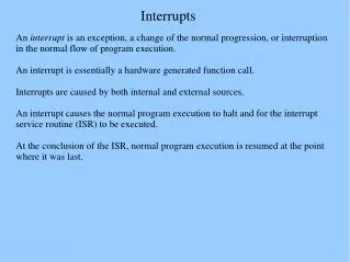
4. INTERRUPTS • 4.2 Interrupts Basics – 2 • On detecting an ‘asserted’ pin, the microprocessor ‘immediately’ stops the execution of the sequence of instructions (task code) to attend to the interrupt: • The microprocessor saves on the stack the address of (what would have been) the next instruction • It saves the ‘active’ registers (those currently in use for the current operation) onto the stack • It jumps to the interrupt service routine (ISR) – written by embedded program developer • Prior to executing the last (RETURN) instruction of the ISR, the microprocessor pops (retrieves) the saved register values from the stack, reloads the PC with the saved address from the stack, and continues execution of the ‘halted’ task code. [The RETURN is either a developer written instruction or a special instruction provided by the microprocessor.] • (See Fig 4-3.)
4. INTERRUPTS • 4.3 The Shared-Data Problem • Shared variables used in both interrupt and task codes for communication • The interrupt routine is activated whenever an event occurs to handle it, caused by either 1) hardware interrupt attached to a sensor or 2) a timer interrupt causing period check or event-occurrence • (See Fig 4.4) • Problem? When interrupt occurs between the two statements • iTemp0 = … set to 73 • (interrupt occurs and handler is invoked to set both iTemperatures [] to 74) • iTemp1 = … set to 74 • If( ) … will be TRUE to cause an alarm, when it shouldn’t
4. INTERRUPTS • The Shared-Data Problem - 1 • Fig 4.5 and Fig 4.6 • Code in Fig 4.5 eliminates setting of local variables, but interrupt can still occur within the if()-statement, causing a false-alarm to be called. • Code in Fig 4.6 lists the assembly version, which shows that an interrupt can occur after the MOVE R1, … instruction and before MOVE R2, …. Since the first MOVE operation takes a few microseconds to execute before the second MOVE operation, enough time for the hardware to assert an interrupt signal • The interrupt routine does not change the values in R1 after the call – saved on the stack
4. INTERRUPT • 4.3 The Shared-Data Problem - 2 • Solving the Shared Data Problem • Use disable and enable interrupt instructions when task code accesses shared data • Code in Fig 4.7 solves the problem, since even if the hardware asserts an interrupt signal to read the new temperature values (in the handler), the microprocessor will complete the task code first • If the task code is in C, the compiler will insert enable/disable instructions in the corresponding assembly code (See Fig 4.8) • If the task code in C doesn’t have enable/disable constructs, then the embedded programmer must use other mechanisms to allow enable/disable of interrupts • Other ways: Atomic or Critical Section code segments for enable/disable interrupt
4. INTERRUPTS • 4.3 The Shared-Data Problem - 3 • Atomic/Critical Section – segment/block of code whose statements must be executed, without interruption because common/shared data is being accessed, in a fixed microprocessor cycles • Needed in task code when variables/data are shared. (Non-shared data can be accessed or processed anywhere else in the task code.) • Fig 4.9 shows an example task code, which can return wrong results if the timer asserts an interrupt during the calculations in the if()-statement • Fig 4.10 is a solution, such that even if the code is called in the critical section of some part of the task code, the enable/disable protections will avoid inadvertent ‘enabling’ of the interrupt in the middle of that critical section • Fig 4.11 lists a solution that works when the assembly code for the return statement is a long-MOVE. It doesn’t if it takes multiple short-MOVE operations • Fig 4.12 lists a solution that reads/re-reads time value without using explicit enable/disable. It works best if compiler optimization is in check to avoid skipping the re-read or while statement by using the volatile keyword to declare the shared data/variable
4. INTERRUPTS • 4.4 Interrupt Latency • How long does it take for my embedded system to respond to external stimulus (or interrupt), when the signal is asserted? • Depends on: • 1. How long is the interrupt disabled (service time or handling time) • 2. Time it takes to execute/handle the higher priority interrupt (than the current one) • 3. Time it takes the microprocessor to save context and jump to the handler • 4. Time it takes the handler to save the context and start ‘responsive’ work • Measuring each of the time periods • 1,2,4: • (i) Write short and efficient code and measure how long it takes to run (system time), eliminating unrelated/auxiliary code (that can be handled differently) from the handler itself • (ii) Look-up and add-up the instruction cycle times for individual instructions • 3: Look-up from the microprocessor manufacturer’s manuals
4. INTERRUPTS • 4.4 Interrupt Latency – 1 • Latency as a function of the time an interrupt is disabled • E.g., given (the following parameters of a system): • Disable time: 125 usec for accessing shared variables in task code • Disable time: 250 usec for accessing time variables/values from a timer interrupt • Disable time: 625 usec for responding to interprocessor signals • Will the system work under these constraints? • Yes, because after the first 125 usec (task code), the timer and processor interrupt requests will be asserted: the next 250 usec the timer is handled, at which point the clock value will be 375 usec. The processor is then handled (after the 250 usec time), for the next 375 usec – plenty of time to finish before the 625 usec deadline. • (See Fig 4.13) • If the microprocessor speed is cut in half, all handling and disabled times will double, and under the same constraints, the system will not work. • Adding a network handler with higher priority (than the processor), will cause latency problems and won’t work (See Fig 4.14)
Figure 4.13 Worst Case Interrupt Latency Processor gets to interprocessor ISR. ISR does Critical work. Task code disables interrupts. IRQ 250 μsec Interprocessor interrupt occurs. 300 μsec Time to deadline: 625 μsec
4. INTERRUPTS • 4.4 Interrupt Latency - 2 • Avoiding the Disabling of Interrupts • Write task and handler code so that both code segments write to, or read from, different parts (buffers) of a shared data structure • Fig 4.15 – Arrays A and B, shared between both codes but never accessed at same time • Fig 4.16 – A queue structure is shared, but task code read from previously written temp values (different cells in the queue), while the handler writes ahead of the task code