UAV Radar System
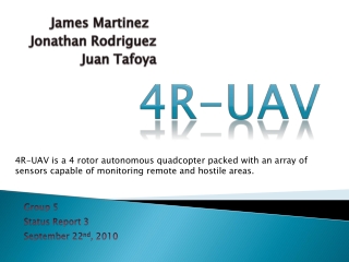
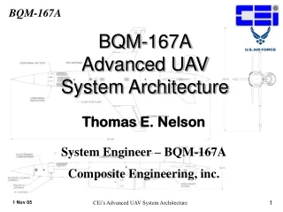
UAV Radar System. Team A: Ned Howard, Brittany Limones , Kenny McChesney , Kelly Rodriquez. Project Overview. Build a miniaturized transmitter and receiver for UAV application Increased operation frequency of 2.3675 GHz Dual-channel instead of multi-channel Project Objectives

UAV Radar System
E N D
Presentation Transcript
UAV Radar System Team A: Ned Howard, Brittany Limones, Kenny McChesney, Kelly Rodriquez
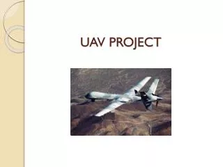
Project Overview • Build a miniaturized transmitter and receiver for UAV application • Increased operation frequency of 2.3675 GHz • Dual-channel instead of multi-channel • Project Objectives • Design Final PCB Board • Test Components Individually • Assemble PCB Board • Test Final PCB Board
Mechanical Design & Construction • Enclosure: Aluminum casing with dimensions 7.52” x 4.252” x 2.308” • Layered slots for PCB boards • Connectors • SMA • Connect to Transmit and Receive Antennas • Ribbon Cable • Supply Power • Control Signals • MCX • Connect to ADC and Frequency Synthesizer
PCB Design • 4-Layer PCB Board: • Rogers R04350: dielectric constant=3.5, thickness=.020 inches • customcircuitboards.com
Testing Procedure • Preliminary Testing • Verify all components behave as expected before building final board • Rogers R04350: dielectric=3.5, thickness=.020 inches • Mechanical Test • Perfecting board size • Placing connector locations • Final Testing • High speed oscilloscope for construction probing • Test by connecting fiber optic delay line to give attenuation • Test entire system
PHA-1+ Amplifier Baseline PHA-1+ Component
EpcosB9496 SAW Filter Custom Board Manufacturer Evaluation Board
Challenges • PCB Design Challenges • Replicating Pads and Vias • Symmetric Channels • Design • IF filtering and amplification stage • Construction • Overcoming surface mounting learning curve