Summer Tasks on UAV Radar
Goddard Space Flight Center. Summer Tasks on UAV Radar. Under supervision of: Shannon Rodr í guez Lihua Li Gerry Heymsfield. Manuel A. Vega-Cartagena UPRM Graduate Student. Objective. NASA IDEAS-ER grant received.

Summer Tasks on UAV Radar
E N D
Presentation Transcript
Goddard Space Flight Center Summer Tasks on UAV Radar Under supervision of: Shannon Rodríguez Lihua Li Gerry Heymsfield Manuel A. Vega-Cartagena UPRM Graduate Student
Objective • NASA IDEAS-ER grant received. • Develop a background on radar design while contributing to the UAV project. Manuel A. Vega-Cartagena
UAV Radar Project • The planned radar will have capabilities of ER-2 Doppler Radar (EDOP). • Nadir beam for vertical winds and precipitation structure. • Conical beam for ocean surface winds and surveillance of the precipitation regions of the storm. Manuel A. Vega-Cartagena
Tasks • Study radar literature. • Redesign UAV’s nadir sub-system RF front end block diagram. • Help bench test UAV’s conical sub-system Tx and Rx paths. • Design 80MHz/5MHz clock PCB. • Design a PCB for UAV’s Vicor power modules. Manuel A. Vega-Cartagena
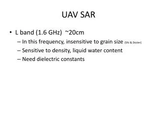
UAV’s RF Front End Block Diagram • Requirements • Magnetron frequency = 9.345 GHz • Intermediate frequency = 60 MHz • Calibration noise injection loop • Receiver noise figure calculations Manuel A. Vega-Cartagena
UAV’s RF Front End Block Diagram Manuel A. Vega-Cartagena
80MHz / 5MHz PCB • Requirements • Single 10MHz sine wave input. • 80MHz and 5MHz TTL clock outputs for DAQ card. • Four amplified analog sensing lines. • Low profile components. • PMC daughter card format. • Original circuit design done by Shannon Rodríguez. Manuel A. Vega-Cartagena
Clock Block Diagram: 80MHz / 5MHz PCB Manuel A. Vega-Cartagena
D-Sub 15 Sense Lines SOIC Components Mezzanine Connectors 80MHz / 5MHz PCB • PCB Construction • Board schematic and layout done with Orcad software. • Built using router in building 22. Manuel A. Vega-Cartagena
80MHz / 5MHz PCB • Board Testing • CPCISYS carrier board with daughter card. • Only DC Power from carrier board used. • Still undergoing debugging process. Manuel A. Vega-Cartagena
~1.3V ~0.4V 80MHz / 5MHz PCB • Test Results • 80MHz Clock Signal Manuel A. Vega-Cartagena
~1.6V ~0.1V 80MHz / 5MHz PCB • 5MHZ Clock Signal SMA Manuel A. Vega-Cartagena
80MHz / 5MHz PCB • Sensing Lines • Two additional lines were added. • Two inverting amplifier stages. • Gain values were changed. Manuel A. Vega-Cartagena
80MHz / 5MHz PCB • Sense Lines • Tested using 10Vpp 1kHz sine wave. • Theoretical voltage gain value = 2.25. • Gain variations may be caused by tolerance in resistances. Manuel A. Vega-Cartagena
Vicor Power Modules PCB • Requirements • Eliminate wire connections between modules. • Reduce mounting time. • Only one board for both +/- voltage configurations. • Output voltages should be accessible and easy to change(+/- 5V, +/-12V, +/-15V). Manuel A. Vega-Cartagena
Vicor Power Modules PCB • Design Schematic • Power modules PCB. • Voltage selection jumper and output. • Wire connections elimination. • Bypass capacitors. • Chassis ground connection. Manuel A. Vega-Cartagena
Vicor Power Modules PCB • PCB Construction • Maximum load currents calculation. • Imax = 5 A @+24VIN for 5V module. • 12V and 15V modules have lower output currents. • Track widths for 10°C temperature increase = 110 mils. • Track clearances for +28V = 29 mils. • Entire design done using standard low-cost 1oz. Cu thickness board. • Components selection. • Connectors with unexposed contacts. Manuel A. Vega-Cartagena
+28V Input Output and Voltage Selection Jumper Chassis Ground Vicor Power Modules PCB • Finished Board Manuel A. Vega-Cartagena
From Aircraft To Components To Power Modules From Power Modules Vicor Power Modules PCB • Power Distribution Matrix • Used to eliminate barrier block. • Makes output voltages more accessible and easy to change. Manuel A. Vega-Cartagena
From Aircraft From Power Modules To Power Modules To Components Vicor Power Modules PCB • Finished Board Manuel A. Vega-Cartagena
Vicor Power Modules PCB • Final Configuration Manuel A. Vega-Cartagena
UAV’s Conical Sub-System Tx and Rx Paths Testing • Task performed to gain hands-on experience. Manuel A. Vega-Cartagena
Learning Experience • Radar Theory Background • RF Front End Design • Power Requirements • PCB Design • ORCAD • Routing machine • Design Implementation Manuel A. Vega-Cartagena
Conclusions • Goals achieved! • 80MHz/5MHz daughter card PCB developed • Power Modules PCB design developed • Gained valuable hands-on experience. Manuel A. Vega-Cartagena
Questions Manuel A. Vega-Cartagena
List of Acronyms • UAV – Unmanned Air Vehicle • IDEAS – Initiative to Develop Education through Astronomy and Space Science • DCAS – Distributed Collaborative Adaptive Sensing • PCB – Printed Circuit Board • TTL – Transistor-Transistor Logic Manuel A. Vega-Cartagena
Acknowledgements • Shannon Rodríguez / 555 • Lihua Li / 912 • Gerry Heymsfield / 613 • Wai Fong / 567 • Gerry McIntire / 613 Manuel A. Vega-Cartagena