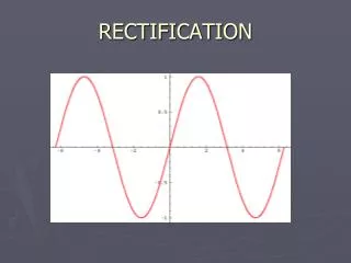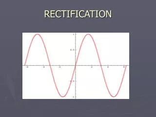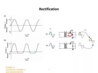
Rectification on YZ plane
Rectification on YZ plane . Rectification on XZ plane . Rectification on XY plane . Detail of the rectified image on XY plane. ONE (OR TWO) VANISHING POINTS GEOMETRY. The original image (Volubilis, Morok). RECTIFICATION. Observation of two families of parallel lines. RECTIFIED IMAGE.

Rectification on YZ plane
E N D
Presentation Transcript
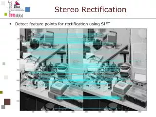
ONE (OR TWO) VANISHING POINTS GEOMETRY The original image (Volubilis, Morok)
RECTIFICATION Observation of two families of parallel lines
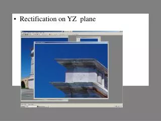
RECTIFIED IMAGE The deformation on the upper line are due to lack of planarity of the mosaic
The Vanishing Point Geometry is a powerful tool. • + • With one Vanishing Point only: the image can be rectified: the ratio base/height is not correct • With two Vanishing Points (one horizontal, one vertical): the image can be rectified: the ratio base/height is not correct • With three Vanishing Points: the image can be rectified, the ratio base/height is correct, the orientation can be assessed, both for the original and the rectified image, apart from one unknown scale factor • - • Camera axis must be very inclined • Only WA are suitable
PhotoModelerby Eos Systems - Canada 8) • A project: from the pictures to the recostruction of the 3-D model • The inverse camera : Determination camera parameters Low-cost software 1000 $
Selection measure unity Options Project:
List Type of camera
camera parameters resolution of the images
Options of the computation Punti omologhi collimati in numero minimo
final model with texture Modello Wireframe
The inverse camera : Unknown camera parameters
constraintsto set Processo vincolato Format .cam
Tests Sintetic image given = -20° = 40° Zc= 3.25
PhotoModeer Dalla deviazione standard (SQM) si è dedotto che nelle collimazioni si ha un’incertezza di 0,6 pixel per unità di misura.
Dalla deviazione standard (SQM) si è dedotto che nelle collimazioni si ha un’incertezza di 0,5 pixel per unità di misura. P F 3
Results: Φ 29.935 deg Expected: 30 deg Results: Φ 15.453 deg Expected: 15 deg θ 9.953 deg 10 deg θ -30.038 deg -30 deg Κ -0.010 deg 0 deg Κ -0.245 deg 0 deg f 27.957 mm 28 mm f 35.001 mm 35 mm ppx 400.546 pxl 400 pxl ppx 394.151 pxl 400 pxl ppy 299.985 pxl 300 pxl ppy 297.443 pxl 300 pxl P F 3 Cubo 100_30_f28 Cubo 60_15_f35
Ancona – Traiano’s arch – Model formation by Photomodeler
Ancona – Traiano’s arch – The residuals of the Model formation
A practical example of 3D- reconstruction The Ho Chi Minh’s house in Hanoi
Left side Front Right side Back sie
inverse Camera Interior camera Parameters stored formato .cam
Some phases of the observation and referencing process Points in 3D space Height of the parapet = 1 Module
PF3 measurements Interior Exterior P F 3 PhotoModeler
PhotoModeler: • utilized by non-specialised operators • very powerful • Very good interface • Many options • 3D modeling • VRML export • Rectification • Non-metric images • Control informations • No need to supply approximate value • Only one control information is missing: the camera station coordinates
9) • ARPENTEUR by Pierre Drap – Pierre Grussenmeyer • (ARchitectural PhotogrammEtry Network Tool for EdUcation and Research). • Designed in 1998 by two research teams (GAMSAU-CNRS and ENSAIS-LERGEC) • Mainly for Education
The running from the net Thus it can be easily and freely used from anywhere, by anybody all over the world and with whatever operating system. www.arpenteur.net. Dedicated to architectural photogrammetry and close range terrestrial photogrammetry, but aerial images (limited to a few Mb) can be also handled.
Photos from a wide range of calibrated cameras metric non-metric camera, digital amateur camera ARPENTEUR permits a better knowledge of basic photogrammetric techniques stereoplotting, image correlation, architectural photogrammetry architectural modelling Output results can then be viewed as text-file, DGN, DXF, VRML file for a further processing with Internet or CAD systems (e.g.: MicroStation, AutoCad).
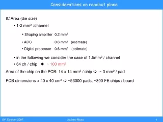
There are today on the market many good products for any purpose and for any pocket The quality of a system is based not only in the accuracy but anso in the efficiency Photointerpretation Orthophoto Conclusions:
Thanks to my students who helped me, part of this material is their graduation thesis: Matteo Cinti, Marco Battistelli Paolo Clini Gianluca Gagliardini Stefano Benassi Paolo Margione Loretta Alessandroni Ivan Catini Floriano Capponi Ingrid Luciani Acknowledgements