Download
1 / 28
280 likes | 300 Vues
Learn about the theory of structures and how to analyze determinate beams to create shear and moment diagrams. Understand the internal reactions and the relationship between load, shear, bending moment, and load distribution.

E N D
TheoryofStructures Analysis of Determinate Beams Shear&Moment Diagrams 1
Beams Members that are slender and support loads • appliedperpendicular to their longitudinalaxis. Concentrated Load,P Distributed Load, w(x) Longitudinal Axis Span,L 2
Typesof Beams • Depends on the support FH Pin configuration FV F V Fixed FH Roller M Fv Roller Pin F H FV 3
Statically Indeterminate Beams ContinuousBeam Propped Cantilever Beam • Can you guess how we find the “extra” reactions? 4
Internal Loadingsdevelopedinastructuremember • in order to properly design structural components, we must know the distribution of the internal forces within the component. In this lecture, we will determine the normal (axial) force, shear, and moment at a point in a structural component. Internal loads at a point within a structural component. For a coplanar structure, the internal load at a specified • • pointwill consistofanormal(Axial)force,N, a shear force,V,andabendingmoment,M. 5
Positive normal (Axial) force, N, tends to elongate the components. Again, note that the normal (axial) forces act in opposite directions on either side of the cut. Positive shear, V, tends to rotate the component clockwise. Note that the shear is in opposite directions on either side of a cut through the component. Positive moment, M, tends to deform the component a dish-shaped configuration such that it would hold water. Again, note that the moment acts in opposite directions on either side of the cut. into 6
Internal Reactions in Beams At any cut in a beam, there are 3 possible • internalreactions required for equilibrium: – – – Normal(Axial)force, Shearforce, Bendingmoment. P a b L 7
Internal Reactions in Beams At any cut in a beam, there are 3 possible • internalreactions required for equilibrium: – – – normal force, shear force, bending moment. Positive Directions Shown!!! M LeftSide of Cut N V Pb/L x 9
Internal Reactions in Beams At any cut in a beam, there are 3 possible • internalreactions required for equilibrium: – – – normal force, shear force, Positive Directions Shown!!! bending moment. V M RightSide of Cut N Pa/L L- x 10
Finding Internal Reactions Pick left side of the cut: • – Findthe sumof all thevertical forces to the left of thecut,includingV. Solveforshear,V. – Findthesumofallthehorizontalforcestotheleft of thecut, includingN. Solve foraxialforce, N. It’s usually, but not always, 0. Sum the moments of all the forces the cut about the point of the cut. Solve for bending moment, M – to the left of Include M. • Pick the right side of the cut: – Same as above, except to the right ofthecut. 11
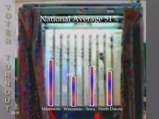
Example: Findtheinternalreactionsat points indicated. Allaxial forcereactionsarezero. Points are 2-ft apart. P = 20 kips 1 2 3 4 5 8 9 10 6 7 8 kips 12 kips 12ft 20 ft Point6 is just leftof Pand Point7is just rightof P. 12
P = 20 kips 1 2 3 4 5 8 9 10 6 7 8 kips 12 kips 12 ft 20 ft 8 kips V x (kips) -12 kips 96 64 80 72 32 48 48 16 24 M x (ft-kips) 13
V & MDiagrams P = 20 kips 8 kips 12 kips 12ft 20ft 8 kips V (kips) x What is the slope -12 kips ft-kips of this line? What is the of this line? slope 96 b 96 ft-kips/12= 8 kips ’ -12 kips M (ft-kips) a c x 14
V & MDiagrams P = 20 kips 8 kips 12 kips 12ft 20ft 8 kips V (kips) x Whatis the areaof -12 kips 96 ft-kips b the blue rectangle? 96 ft-kips What is the area of the green rectangle? -96 ft-kips c M (ft-kips) x 15
Draw Some Conclusions The magnitude of the shear at a point equals the slope of the moment diagram at that point. The area under the shear diagram between two points equals the change in moments between those two points. At points where the shear is zero, the moment is a local maximum or minimum. • • • 16
The Relationship Between Load, Shear Bending Moment and w(x)theload function V(x) w(x)dx M(x)V(x)dx 17
Shear Force & BendingMomentDiagram Structureunderloads dVw Slope ofV=load dx Shearforcediagram dM V Slope of M = V dx Bending moment diagram 18
Common Relationships Load 0 Constant Linear Shear Constant Linear Parabolic Moment Linear Parabolic Cubic 19
Common Relationships Load 0 M 0 Constant Shear Constant Constant Linear Moment Linear Linear Parabolic 20
Example: DrawShear& Moment diagrams for the following beam 12 kN 8 D kN A C B 1m 3 m 1m RA = 7 kN RC = 13 kN 21
12 kN 8 D kN A C B 1 m 3 m 1 m 8 7 8 7 V (kN) -15 -5 7 M (kN-m) 2.4 m -8 22
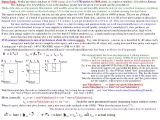
The reactions are VL = 75kN, VR = 105kN, and HL = 0. 75 kN 105kN Because the form of the loading does not change anywhere along the beam, single equationswillsufficeformoment and shear: ∑Fy=0;75-10*x-20/(2*9)*x^2 ∑M=0;75*x-5*x^2-(10/27)*x^3 23
Shear and moment are plotted : 75 55 35 15 -5 -25 -45 -65 -85 -105 Shear Diagram 0 1 2 3 4 5 6 7 8 9 220 200 180 160 140 120 100 80 60 40 20 0 0 1 2 3 4 5 6 7 8 9 24
Examples 25
4-Developequations forshearand momentas a function of positionfor the following structural components. Plot the functions. 9 m 27
Any questions? 28