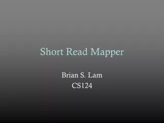
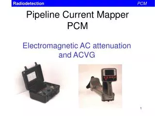
Pipeline Current Mapper PCM
Radiodetection PCM. Pipeline Current Mapper PCM. Electromagnetic AC attenuation and ACVG. Radiodetection PCM. PCM Application. PCM will find: Coating defects (holidays) Shorts to other structures. Radiodetection PCM. Transmitter. High power output (150 Watts)

Pipeline Current Mapper PCM
E N D
Presentation Transcript
Radiodetection PCM Pipeline Current MapperPCM Electromagnetic AC attenuation and ACVG
Radiodetection PCM PCM Application • PCM will find: • Coating defects (holidays) • Shorts to other structures
Radiodetection PCM Transmitter • High power output (150 Watts) • Very low frequency to • increase range • reduce coupling to other services • reduce field distortion
Radiodetection PCM Transmitter • Powered from a transformer/rectifier site. • From either rectified DC (20 – 50 V) or 110/240 VAC.
Radiodetection PCM PCM Receiver • Identifies signal from Transmitter • Converts to Current • Log to 400 records and download to PC • Connect to GPS
Radiodetection PCM A-frame • Pinpoint holidays • Known as ACVG • ...but SAME results as DCVG.
Radiodetection PCM Transmitter Connection • Typical Transmitter to pipe connection • Provides a perfect pipe connection point • Anode provides perfect ground connection point
Radiodetection PCM Transmitter Connection • Disconnect Rectifier • Use same connections to connect the PCM transmitter
Radiodetection PCM Transmitter Connection • Always direct connect • Always use an independent ground - Anode Bed - Ground Stake - Across an insulator? • Always have a map of the facility • Never use another utility as the ground return. • Never assume anything.
Radiodetection PCM • Locating Shorts • - First signal loss may not be the short. • - There may be more than one short. • - There may be an unknown source. • Locating Coating defects • - Take readings at the same intervals. • - Make sure PCM and boot is perpendicular to the pipe. • - Hold unit steady and upright when reading current. • You do not always have to connect closest to the suspected short or coating defect. • More is not always better.
Radiodetection PCM Setting the Transmitter • Three settings available • ELF (4+98 Hz) • ELF + CD (8 Hz) • LF (512 H z) + CD • Normal set to ELF + CD
Radiodetection PCM Setting the Transmitter • Set Current switch to desired current
Radiodetection PCM Taking Current Readings • If ELF and arrows selected on Tx then select ELF on the RX • Locate pipe in conventional way
Radiodetection PCM Taking Current Readings • Hold the Receiver Steady on the ground and press the PCM Key. • Current is displayed after ~ 4 s
Radiodetection PCM Taking Current Readings • Unit automatically performs steps: • narrow band signal processing measures 4 Hz signal (magnetometer); • proceed to calculate depth (twin aerials); • calculate current; • determine CD (using 4 Hz + 8 Hz shift).
Radiodetection PCM Current Direction • Indicates which direction the Current is flowing • Aids fault analysis
Radiodetection PCM Methodology using PCM for Current Surveys • Use an independent ground and try to mimic your CP circuit when possible • Make sure rectifiers are not influencing the signal (turn off AND disconnect if necessary) • Isolate your circuit whenever possible (disconnect bonds for better surveys) • Take readings at equal distances and record your distances • Every 50 feet is a good standard (others can be used dependant on location) • Use it as a macro tool and depth of cover tool (use A-frame for micro) • Look for anomalies with more than a 5% change normally • Make sure unit is upright and perpendicular to the pipe • Use the peak mode. Check peak and null readings and verify depth when readings are suspect. • Take multiple readings in one location if you suspect the accuracy. • Know what is in the area of your pipe and what it is connected to it
Radiodetection PCM Datalogging • 400 records can be stored. • Records can be: • reviewed on PCM • downloaded to a PC • Records can be viewed on Excel
Radiodetection PCM Datalogging
Radiodetection PCM A-frame
Radiodetection PCM A-frame
Radiodetection PCM PCM with A-frame for Alternating Current Voltage Gradient Surveys • Used as a micro and a macro survey tool • Can be used in various soil conditions but ground contact of the probes will affect the readings • Rectifiers generally do not influence the ACVG survey • In areas of high interference or where current survey does not give you answers, ACVG can still be used with more success • Know what is in the area of your pipe and what is connected to it • Larger holidays can mask smaller ones until the larger holidays have been repaired • PCM displays A-frame readings in db or decibels. Remember every 10 db higher is twice as large • Metal to dirt contact and soil resistance (not necessarily size of holiday) is what affects the db readings
Radiodetection PCM ACVG Methodology • Use an independent ground and try to mimic your CP circuit when possible • Take readings parallel and along the pipe. When you see an arrow reversal go perpendicular to the pipe and make sure arrow reverses over pipe • You do not have to be right on top of the pipe when surveying • On concrete and asphalt use wet sponges or rags on the probes or wet the ground around the probes. • Take readings at equal distances usually about every two to three steps • Use the largest db reading seen around the anomaly for you records • Record all faults seen with db readings and footages or GPS coordinates. • Once done, anomalies can generally be categorized into 4 areas • 80db – 100db – large • 65db – 80db – medium • 50db – 65db – small • 50db and below – very small • LOCAL CONDITIONS DETERMINE WHAT IS A DIG!
Radiodetection PCM Graphing in Excel and Data Interpretation
Radiodetection PCM Graphing in Excel and Data Interpretation
Radiodetection PCM Graphing in Excel and Data Interpretation
Radiodetection PCM Graphing in Excel and Data Interpretation
Radiodetection PCM Graphing in Excel and Data Interpretation
Radiodetection PCM Graphing in Excel and Data Interpretation
Radiodetection PCM Graphing in Excel and Data Interpretation