Basic PCM
Basic PCM. Why Telecom more Popular. CC- Country Code AC- Area Code DN- Directory No. Electronically dist=0 Answer only Charge Tell No. 15 digits (Universal). CC. DN. AC. Demarcation of Telecom. Transmission. Cont…. Sampling Theorem BL Signaling Fs ≥ 2fm. 3.


Basic PCM
E N D
Presentation Transcript
Why Telecom more Popular CC- Country Code AC- Area Code DN- Directory No • Electronically dist=0 • Answer only Charge • Tell No. 15 digits (Universal) CC DN AC Demarcation of Telecom • Transmission
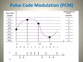
Cont… • Sampling Theorem • BL Signaling • Fs ≥ 2fm 3. Problem to achieve Digital Tx Noise The Samples cannot be Reproduced Tr Media Tx Rx Media Attenuation Find a technique Digital Tx (1) Tx Info • Rx Info • Verify the Rx Info Verification Difficult
Cont… • Quantizing • Equate the sample to a quantize level. • Then transmit verification will be easy at the receiver • Quantizing noise is inevitable • Encoding • Convert this quantized level in to binary level • Verification will be more easy
Quantizing the samples will be equate to 1/256 levels In linear quantizing S/N is good only for high valued samples and 90% of the samples are within ½ of maximum voltages Hence linear quantizing is not used. Hence Quantizing Noise (∆V) is inherent in PCM transmission, since there is a difference between actual sample to Quantized level.
Exercise 1:Convert the following denary numbers to binary(Don’t use the method of dividing by 2, use the finger method) • (a) 5 (g) 520 • (b) 9 (h) 1028 • (c) 16 (i) 2050 • (d)33 (j) 4100 • (e) 67 (k) 8200 • (f) 120 (l) 16401
Answer to Exercise 1 • (a) 5=101 (b) 9=1001 • (c) 16=10000 (d)33=100001 • (e) 67=1000011 (f) 120=1111000 • (g) 520=1000001000 (h) 1028=10000000100 (i) 2050=100000000010 (j) 4100=1000000000100 • (k) 8200=10000000001000 (l) 16401=100000000010001
Exercise 2Convert the following from binary to Denary(Using fingers only) • (a) 101 • (b) 110 • (c) 1001 • (d) 11101 • (e) 100000 • (f) 1011010 • (g) 111000111
Answers to Exercise 2 • (a) 101 5 • (b) 110 6 • (c) 1001 9 • (d) 11101 29 • (e) 100000 32 • (f) 1011010 90 • (g) 111000111 455
Exercise 3Convert the following denary numbers to hexa and then to binary • (a) 9 • (b) 20 • (c) 36 • (d) 129 • (e) 518 • (f) 1030 • (g) 4095 • (h) 8200
Answers to Exercise 3 • Denary Hexa Binary • (a) 9 9 1001 • (b) 20 14 10100 • (c) 36 24 100100 • (d) 129 81 10000001 • (e) 518 206 1000000110 • (f) 1030 406 10000000110 • (g) 4095 FFF 111111111111 • (h) 8200 2008 10000000001000
The A law Signaling Compression and Characteristics Less levels are located for height valued samples
Cont… Note : A Total of 256 quantisation steps covers line peak to peak range of nomal speech intensities A law gives lower quantising dislortion …. Law There are 16 segments shown in this graph positive 0,1 and negative 0,1 consai one linear segment. hence there are 10 linear segments. A B C S W X Y Z Encoded 8 bit format Sign No of seg No of pos in the Segment If S=1 it is positive sample If S=0 it is Negative sample Vm – Maximum voltage = 3072 mv N – Na of quantised levels =256 Some times ’A’ low is named as Eurpean law (C.E.P.T) Equation for logaribimic part y=n ln Ax / ln A (1/A<x<1) Linear part y=Ax (0<x<1/A)
Encoding • The quantized level is then converted in to 8 bits. This 8 bits represent, • S ABC WXYZ • S = sign + or - • ABC = No of segments • WXYZ = No of level in that segments • Summary of process involved, Convert equate To a quantize level 1/256 8 bit Sample
Convert the following samples into encoded format and calculate the signal /noise ratio • 700mV -400mV 300mV • 100mV 1515mV -95mV
Answers • 700mV -400mV 300mV • 11011101 01010001 11001001 175 50 ∞ • 100mV 1515mV -95mV 10110001 11110000 0011000 25 72 295
WAVE FORMS IN THE TRANSMISSION LINES • RZ return to zero wave form • NRZ non return to zero wave form • RZ, NRZ AMI WAVE FORMS • CONCEPTS OF TRANSCODING • SPECTRUM ANALYSIS OF PRACTICAL WAVE FORMS • HIGH DENSITY BIPOLAR 3 CODE
Transcoding Code Conversion to suit for the Transmission media Out put of a PCM System either RZ, NRZ 1 bite named as mark NRZ means, Mark will return to zero before the period of CLK pulse, but at the period of the click pulse. RZ, means mark will NOT come to zero before the period of the CLK pulse, but at the period of the CLK pulse if the following is not a MARK.
Question ? Q 1. 1. List out the different phases of a call? 2. Label the voice time slots? 3. Draw the messages exchange with regards to successful call? 4. Calculate the time taken to establishment the call? 5. Assuming each call will establish for 3 minutes conversation time. How many conversations can be establish? 6. Discuss how this concept is extend the packet switching networks? Q 2. Draw 101101 in NRZ and RZ and in AMI format
Answer Q2. NRZ RZ
Practical Transcording wave Forms High Density Bipolar 3. Rules 1. Don’t allow more than 3 Consecutive Zero’s to be present in the wave form (media). Introduce a violation bit. Violation bit has to be of the same polarity of the previous MARK. 2. Two Consecutive violation bits has to be of opposite polarity. 3. Between two consecutive violation bits if there are even number of last violation will be boove where B is the stuffing BIT and will be of opposite polarity to the previous MARK. Process Involved
HDB3 Rules Rule 1 : Don’t allow more than 3 corrective zero’s to be present in the wave form, for the 4th zero introduce a violation bit Assume the bit stream is as follows, 100001 Normally 1+oooo1- Under HDB3 before transmitting convert the bit stream, according to rules, 1+000 1+ 1- Then transmit assume the same bit stream received How the receiver detranscode - 1+0001+1- If knows it is a violation hence convert to 100001 1+0001+1- Transmitted bit stream has been received correctly 0
Then above rule is easily followed when there are odd number of marks between two consecutive violation bits Rule 2 : Two consecutive violations bits of opposite polarity • 0 1000 0 1 • 1+0001+1-0001-1+ • 1+0001+1-0001- Try : 10000100001 Convert HDB3 Transmit Can be easily convert back to 10000100001
But, if there are even number of marks between two consective violation bits addition sub rule to be introduce to follow above rule 2. for the last four zero’s introduce the pattern as B 0 0 V where B is the bit, where it is opposite sign to the previous mark Assume 100001100001 1+0001+1-B+00V-1+ 1+000V+ 10000 But next stream 1-1+001- After two zero another violation Hence the reciver willl correct this as, 100001
SIGNALLING • BASIC CONCEPTS OF ANALOGUGE TYPE OF SIGNALLING • HOW ANALOUGE TYPE OF SIGNALLING ADOPTED TO PRIMARY PCM • CHANNEL ASSOCIATED SIGNALLING • BASIC FUNCTIONAL BLOCKS IN PCM ADOPTED FOR ANALOUGE TYPE OF SIGNALLING • COMPONENTS OF A PCM EQUIPMENT
Cont… Supervisory Signaling Analog • Characteristics • Supervisory is always present with voice. • Register is always prior to voice hence analogue channel • exchange will be as follows. • Exchange to another exchange will be as follows Register V = Voice R = Register Sup. Signals are on M, E, Wires
Cont… • Multiframe in a PCM SYSTEM for supervisory signals only • TS16 is available. CCJTT has allocated 4bits for each channel. • To send 30 channels supervisory signals on TS16, You need • 15 frames. • To align SIG TR module to SIG RX module one TS16 is used. • Hence Multiframe consist 16 Frames. f0 MF Sys f1 CH1 CH17 f2 CH2 CH18 2 ms f15 CH15 CH31
Structure of Multiframe One Multiframe= 16 Frames TS 17-31 TS 1-15 Practical Channels TS 16 TS 0 1 2 TS 0 TS 0 TS 0 15 17 31 F0 TS16 is used for Multiframe alignment all other TS16 are used for Channel Associated signaling There are two kinds of synchronization words odd and even Odd actually synchronization Even alarm signaling