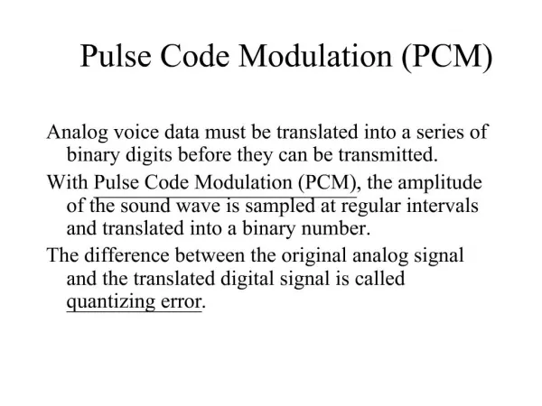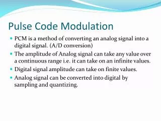
Pulse Code Modulation (PCM)
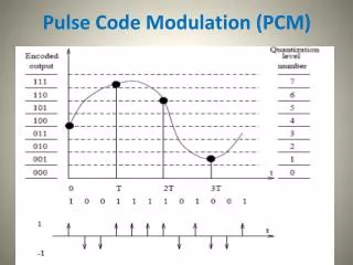
Pulse Code Modulation (PCM). Example. Solution. In the previous example we have 8-quantization levels (to encode with 3-bits) from code number 0 to 7 (from binary code 000 to 111) Sample value : 2.8 3.2 2.7 1.1 Nearest level : 3 3 2.5 1

Pulse Code Modulation (PCM)
E N D
Presentation Transcript
Solution In the previous example we have 8-quantization levels (to encode with 3-bits) from code number 0 to 7 (from binary code 000 to 111) Sample value: 2.8 3.2 2.7 1.1 Nearest level: 3 3 2.5 1 Code number: 6 6 5 2 Binary code: 110 110 101 010
PCM Transmitter Block Diagram n L r=nfs
The most important feature of PCM systems is the ability to control the effects of distortion and noise.A PCM signal may be reconstructed from the distorted and noisy input by means of regenerative repeaters placed sufficiently close to each other along the transmission route
Transmission Bandwidth of a PCM Wave • Each encoded message sample is represented by a n-digit code word. Consequently, the signal bit rate (r) becomes r = n fsfs ≥ 2 W, Where: W= The message B.W. , fs= Sampling rate • The transmission bandwidth (BT) required by the PCM wave is:
Main feature of pulse-code modulation • If the regenerators are well placed then they cancel the effect of channel distortion and noise. • In this case the only source of distortion and noise is the quantization error
For example We multiplex two signals g1(t), and g2(t) Ts Tx
A A M U X D E M U X … A1 B1 C1 A2 B2 C2 … B B C C TDM: - Multiple data streams are sent in different time in single data link/medium - Data rate of the link must be larger than a sum of the multiple streams - Data streams take turn to transmit in a short interval - widely used in digital communication networks
Define Ts = sampling interval (period) fs = sampling frequency (rate) Tx = time spacing between adjacent samples in the TDM signal waveform • Consider two cases: • Equally sampled ( N of input signals ) Tx= Ts /N N : number of samples • Non equally sampled Signals have non equal bandwidths
The resultant signal could be considered as a new one sampled with fx . To get the B.W. of the TDM-PAM signal: The used system must have a minimum B.W. equals to fx / 2 in order to pass the TDM-PAM signal. The B.W = K fx (½) < K < 1 Minimum Bandwidth
Equally sampled signals • Example-2 Two signals each band-limited to W = 3 KHz N = 2 signals • Ts = 1 / ( 2W) = ( 6000)-1 = 166.7 μ sec. • Tx = Ts / 2 = 83.3 μ sec. • B ≥ ( 1 / 2Tx ) ≥ 6 KHz • N.B. PAM is as efficient in conserving bandwidth as SSB when all the signals have the same bandwidth.
Example-3 If we have 20 signals each band-limited to 3.3 KHz sampled with rate 8 KHz and PAM-TDM is used. Find the min. clock freq. and min. B.W. Solution: Clock frequency fx=8K20=160 KHz Min. B.W.=fx/2 =80 KHz If PCM-TDM is used using 3-bits/sample: The bit rate = 8K 203 = 480 Kb/s
Non-equally sampled signals • For signals having non equal bandwidths we do non equal sampling • To conserve B.W. PAM time multiplexed systems usually group input signals of comparable bandwidths
3 3 1 2 • Examplethree signals band limited to W , W and 2W • Equally Sampled: • fs = 4 W • Ts = 1 / 4 W • Tx = 1 / 12 W • fx = 12 W • B = fx/2 = 6 W > SSBB.W.
1 3 1 3 2 • Non equally sampled • Ts = 1 / 2W • N = 4 • Tx = 1/(8W) • B = 4W • = SSB B.W.
1 6.312 Mb/s T2 1 PCM Mux 2 M12 Mux M23 Mux 1 1 2 M34 Mux 2 2 24 4 7 6 274.176 Mb/s 1.544Mb/s T1 44.736 Mb/s T3 T4 Example of non equally sampling T1– Digital System North American Digital Hierarchy
MultiplexingPCMsignals • 24 – analog signals each band-limited to 3.3 K sampled at a rate of 8 K. Frame time=125 s • At 6000 ft, repeaters are used • Each sample is encoded by 8-bits • No. of levels = 256 level • No. of bits /frame = (24 8) + 1F bit = 193 bits Where: 1F is one frame synchronization bit • Bit rate for T1 channel =(193 8K)=1.544 Mb/s
Multiplexing T1-Lines • 4-T1 lines are multiplexed to generate one T2 line. • M12 multiplexer adds 17 bits for synch. • Number of bits/frame = (193 4) + 17 = 789 bits/frame • Bit rate for T2 =789 8K = 6.312 Mb/s
Multiplexing T2-Lines • 7-T2 lines are multiplexed to generate one T3 line. • M23 multiplexer adds 69 bits for synch. • Number of bits/frame = (789 7) + 69 = 5592 bits/frame • Bit rate for T3 = 5592 8K = 44.736 Mb/s
Multiplexing T3-Lines • 6-T3 lines are multiplexed to generate one T4 line. • M34 multiplexer adds 720 bits for synch. • Number of bits/frame = (5592 6) + 720 = 34272 bits/frame • Bit rate for T4 = 34272 8K = 274.176 Mb/s
Line Coding • How to represent the ‘1’ and ‘0’ • Each line code has its advantage and disadvantage • A good line code should have the following requirements:
Requirements of line code: • Transmission bandwidth : as small as possible • Error detection and correction • Avoid D.C. ( due to the A.C. coupling used at the repeaters • Adequate timing content: It should be possible to extract timing or clock information from the signal • (long sequence of zeroes could cause errors in timing extraction for certain line codes)
Line Codes 1 0 0 0 1 1 1 1 1
Examples • On/Off (unipolar) • “1” send p(t), “0” nothing • Return to zero (RZ) • Non-Return to Zero (NRZ) • Polar (bipolar) • “1” send p(t), “0” send -p(t) Bipolar (RZ) Bipolar (NRZ) 1 1 1 0 0 1 1 1 1 1 0 0 1 1 1 1 1 0 0 1 1 1 1 1 0 0 1 1
Bipolar Alternate Mark Inversion (AMI): • “0” has no pulse • “1” changes the sign of the waveform p(t) 1 1 1 0 0 1 1
Bi-phase Codes (Manchester) • More complex waveforms can “split” the phase of the two signals 1 1 1 0 0 1 1