

Wiring Diagram
E N D
Presentation Transcript
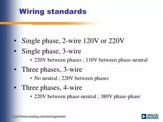
Wiring Diagram • The overall wiring diagram will resemble this structure. The power board will be extremely similar to that of TigerBot #3. The difference lies in that our power board will not have the current sensing to each limb but a totally separate board. The servos, microcontrollers, sensors, and will still be powered from this board but in a slightly different configuration. The design for this board can be seen below. The foot sensor boards are also going to be used from Tigerbot #3.
Servo Information • This software allows a full simulation of motion. Motion files can be created to re-enact movements of the robot. Some examples include the “Low crouch”, “Leg Lift”, and “Pick Itself Up”. The majority of the initial simulations are for mechanical qualifications and will be covered in the Mechanical/Industrial engineering portion of the design review. However, the next step in this process is to implement Inverse Kinematics to develop a walking algorithm that also supports the mechanical design parameters. Below is the extensive characterization conducted on the servos, done by Alexander Yevstifeev last quarter.
Locomotion.c /** *Controls the robots locomotion *with more functions added depending on the task **/ #include "Locomotoin.h" void walk(){ } void stand(){ } void balance(){ }
Locomotion.h #ifndef LOCOMOTION_H #define LOCOMOTION_H void walk(); void stand(); void balance();
RobotStatus.c /** * Checks the robots status to begin movements * different types of check depending on the situation **/ #include "RobotStatus.h" intcheckBalance(){ return 0; } intfrontClear(){ return 0; } intcurrentServoPosition(int Servo){ return 0; }
RobotStatus.h #ifndef ROBOT_STATUS_H #define ROBOT_STATUS_H intcheckBalance(); intfrontClear(); intcurrentServoPosition(int Servo);
Sensors.c /** * Class to return data from all the sensors **/ #include sensors.h intcheck_IR( intIRnumber ){ int value = 0; switch(IRNumber){ case 0: break; case 1: break; case 2: break; case 3: break; case 4: break; case 5: break; case 6: break; default: break; } return value; } intcheck_IMU(void){ return 0; }
Sensors.h #ifndef SENSOR_H #define SENSOR_H intcheck_IR( intIRnumber ); intcheck_IMU(void);
ServoControl.c /** *Control the servos, can be added to locomotion maybe depending *on what else might be needed in this class. **/ #include "ServoControl.h" void setServo( intServoNumber, int position ){ switch(ServoNumber){ case 0: break; case 1: break; case 2: break; case 3: break; case 4: break; case 5: break; case 6: break; case 6: break; default: break; } }
ServoControl.h #ifndef SERVO_CONTROL_H #define SERVO_CONTROL_H void setServo( intServoNumber, int position );
Compile Script #!/bin/bash rmServoTestCode; g++ -static -I /home/roboard/RobotCode/RoBoIO/libsrc/ -c ServoTestCode.cpp -o ServoTestCode.o g++ -o ServoTestCodeServoTestCode.o -static -L /home/roboard/RobotCode/RoBoIO -l RBIO ./ServoTestCode;
Servo Test Code #include <stdio.h> #include "roboard.h" #include "rcservo.h" #include <unistd.h> int main(void){ roboio_SetRBVer(RB_100RD); unsigned long motion_frame[2] = {0,0}; if(rcservo_SetServo( RCSERVO_PINS1, RCSERVO_SERVO_DEFAULT_NOFB )){ puts("Servo 1 set correctly"); } if(rcservo_SetServo( RCSERVO_PINS2, RCSERVO_SERVO_DEFAULT_NOFB )){ puts("Servo 2 set correctly"); } while(1){ if(rcservo_Init(RCSERVO_USEPINS1 + RCSERVO_USEPINS2)){ puts("Victory"); rcservo_EnterPlayMode_HOME(motion_frame); rcservo_MoveTo( motion_frame, 500 ); if(motion_frame[0] == 0){ motion_frame[0] = 1500; motion_frame[1] = 1500; }else{ motion_frame[0] = 0; motion_frame[1] = 0; } rcservo_Close(); }else{ puts("Could not init Servo"); puts(roboio_GetErrMsg()); sleep(1); } } return 0; }
Example Inverse Kinematics Code %Inverse Kinematics Function. Computes 6 output angles given foot position %and orientation. %written by Alexander Yevstifeev %Based on work in the paper Closed-form Inverse Kinematic Joint Solution for Humanoid Robots by Muhammad A. Ali, Andy Park, and C.S. George Lee. function [T] = Leg_Inv_Kin(rx,ry,rz,p) %outputs joint angles for T(1)-T(6) of a humanoid leg given the x,y,z axis %rxryrz are rotation angles for orientation and a position vector. %order of angle joints from T(1) to T(6) are leg twist, leg side, leg lift, knee, foot lift, and foot tilt. %Link length definitions L5 = 0.05 ; % Link between ankle and bottom of foot L4 = 0.25 ; % Link between knee and ankle L3 = 0.25 ; % Link between hip and knee %compute rotation matrix given rotation angles rx, ry, and rz Cx = cos(rx) ; Sx = sin(rx) ; Cy = cos(ry) ; Sy = sin(ry) ; Cz = cos(rz) ; Sz = sin(rz) ; Rmat = [ Cy*Cz , -Cx*Sz+Sx*Sy*Cz , Sx*Sz+Cx*Sy*Cz ; ... Cy*Sz , Cx*Cz+Sx*Sy*Sz ,-Sx*Cz+Cx*Sy*Sz ; ... -Sy , Sx*Cy , Cx*Cy ; ] ;
Example Inverse Kinematics Code %build location matrix, find inverse, assign inverse vectors M = cat(2, Rmat , p') ; M = cat(1,M,[0 0 0 1]) ; Mi = inv(M) ; s = 1:3 ; ni = Mi(s,1)' ; si = Mi(s,2)' ; ai = Mi(s,3)' ; pi = Mi(s,4)' ; C4 = ( (pi(1)+L5)^2 + pi(2)^2 + pi(3)^2 - L3^2 - L4^2 ) / (2 * L3 * L4 ) ; T(4) = atan2(sqrt(1 - C4^2),C4) ; S4 = sin(T(4)) ; psi = atan2( S4 * L3 , ( C4 * L3 ) + L4 ) ; T(5) = atan2( -pi(3) , sqrt( (pi(1) + L5)^2 + pi(2)^2 ) ) - psi ; C5 = cos(T(5)) ; T(6) = atan2(pi(2) , -pi(1) - L5 ); if (cos(T(4)+T(5))*L3 + C5*L4) < 0 T(6) = T(6) + pi ; end S6 = sin(T(6)) ; C6 = cos(T(6)) ; T(2) = atan2( -S6*si(1) - C6*si(2) , -S6*ni(1) - C6*ni(2) ) ; T(1) = atan2( sqrt(1 - (S6*ai(1) + C6*ai(2))^2) , S6*ai(1) + C6*ai(2)); if sin(T(2)) < 0 T(1) = T(1)+3.14159 ; end T(3) = atan2(ai(3) , C6*ai(1) - S6*ai(2) ) - T(4) - T(5) ; %Adjustment for reference frames on model T(1) = -(T(1)+1.5707); T(2) = -(T(2) + 1.5707) ; T(3) = T(3) - 1.5707 ; T(6) = -T(6) ; %correction for position value over 2*pi for i = 1:6 ; T(i) = rem(T(i),6.283) ; end end
analogRead() (arduino function) • Reads the value from the specified analog pin. The Arduino board contains a 6 channel (8 channels on the Mini and Nano, 16 on the Mega), 10-bit analog to digital converter. This means that it will map input voltages between 0 and 5 volts into integer values between 0 and 1023. This yields a resolution between readings of: 5 volts / 1024 units or, .0049 volts (4.9 mV) per unit. The input range and resolution can be changed using analogReference(). • It takes about 100 microseconds (0.0001 s) to read an analog input, so the maximum reading rate is about 10,000 times a second.
Current Bill of Materials • Left to order • Wireless module for Roboard (about $50.00) • Roboard Servos (10, possible discount?)