Understanding Sequential Systems and Basic Latches: SR Latch, D-FF, and JK-FF
This guide covers the fundamentals of sequential systems, highlighting the differences between combinational and sequential systems. It introduces key components like latches and flip-flops, emphasizing their dependence on current states and inputs. Learn about the Set/Reset NOR latch (SR latch) and its operations, along with the various types of flip-flops, including the clocked D flip-flop, T flip-flop, and JK flip-flop. The document further explores timing diagrams, characteristic equations, and state tables critical to understanding these memory devices.

Understanding Sequential Systems and Basic Latches: SR Latch, D-FF, and JK-FF
E N D
Presentation Transcript
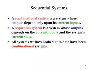
Sequential Systems • A combinational system is a system whose outputs depend only upon its current inputs. • A sequential system is a system whose outputs depends on the current inputs and the system’s current state. • All systems we have looked at to date have been combinational systems.
Flip-Flops/ Latches • Latches and Flip-Flops are devices that can have two internal states (0,1) • The output of a latch or a Flip-Flop (FF) is dependent upon its CURRENT STATE and CURRENT INPUTS. • Latches and FF’s are the simplest examples of sequential systems.
Set/ Reset Nor Latch (SR Nor Latch) Present State Next State S R Ps NsL L Q QL H X LH L X HH H X - S R Ps Ns0 0 Q Q0 1 X 01 0 X 11 1 X - R S Q Q R Q’ Symbolinputs,outputs high true. Q’ S Implementation
Set/ Reset Nor Latch (SR Nor Latch) S R Ps Ns0 0 Q Q0 1 X 01 0 X 11 1 X - S Q R Q’ Not Allowed Operation Example:
SR latch Operation 1 0 0 1 R=0 1 R=0 Q Q 1 0 1 0 Q’ Q’ S=0 S=0 1 1 0 0 1 RESET operation SET operation
SR latch Operation (cont) 0 1 R=0 R=0 Q Q 1 0 0 1 Q’ Q’ S=0 1 S=0 0 Stable when S=R=0, Q’=1 Stable when S=R=0, Q=1
What about S=R=1? (Set,Reset both true?) R=0 1 1 0 0 Q 1 0 Q’ S=0 1 0 Assume that S, R both transition to 1 simultaneously. Q becomes ‘0’, but Q’ remains ‘0’! Outputs are no longer complements of each other.
What happens when S,R return to 0? Q R=1 0 0 1 0 1 0 1 0 1 0 1 0 1 Q’ S=1 0 Oscillation occurs if S,R return to 0 simultaneously! At some point the system will settle into a stable condition. The bottom line is that S=R=1 is an illegal input condition (or design the SR latch such that one input is DOMINANT).
SR Latch, R dominant R Q Q’ S S R Ps Ns0 0 Q Q0 1 X 01 0 X 11 1 X 0 When S=R=1, then acts as a RESET (R is dominant)
SR Nor Latch -- Characteristic Equation Not Allowed
Terminology • A bistable memory device is the generic term for the elements we are studying • We can use the term latch or flip-flop to refer to these devices • latch: bistable memory device with level sensitive triggering (no clock) • flip-flop: bistable memory device with edge-triggering (with clock) • Warning: Your author (Roth) uses the terminology Flip-Flop and Clocked Flip-Flop instead of latch and Flip-Flop • latch, flip-flop more standard
Data Flip-Flop (D-FF, falling edge triggered) Only time D-FF changes state is on a CLOCK EDGE. This D-FF is falling edge triggered. Changes state to whatever the D value was just before the clock neg. edge occurred. (Q+ = D) CK D Ps Ns0 X Q Q1 X Q Q10 D X D D Q CK is the clock input. D input is only sampled at a clock edge. CK Q’
A Clock Waveform Pw rising edge falling edge - period (in seconds) voltage Pw - pulse width (in seconds) time f = 1/ f- frequency pulse width (in Hertz) duty cycle = Pw / duty cycle- ratio of pulse width to period (in %)
D-FF Operation Example 1 D CK Q On falling edge of C, D=0, so Q=0 On falling edge of CK, D=1, so Q=1
Clocked T Flip-Flop (falling edge triggered) CK T Ps Ns0 X Q Q1 X Q Q10 0 Q Q10 1 Q Q’ Retain State Synchronous Toggle T-FF CK is the clock input. T input sampled only at a clock edge. T Q CK Q’
Clocked T-FF Operation Example T=1Toggle T=1Toggle T=0, RetainState
Clocked JK Flip-Flop (falling edge triggered) CK J K Ps Ns0 X X Q Q1 X X Q Q10 0 0 Q Q 10 0 1 X 010 1 0 X 110 1 1 Q Q’ Retain State Synchronous Reset Synchronous Set Synchronous Toggle J Q CK is the clock input. J,K inputs are sampled only at a clock edge. CK K Q’
Clocked JK-FF Operation Example J=1, K=1Toggle J=0, K=1Reset J=1, K=0Set
JK-FF Implementation K Q D Q J CK CK Q’ This is a falling edge triggered JK-FF. We will derive this implementation at a later date.
P J S S Q Master Slave P’ Q’ K R R Master-Slave JK-FF Implementation
Clocked FF’s with Asynchronous Preset and Clear Inputs Q’ Q Q’ Q CLR PRE CLR CK CK K J D The small inversion symbol on the preset and clear inputs indicate that these are active for a 0 state. These inputs are asynchronous, meaning that they override the clock and JK inputs (or clock and D inputs). CLR active Q = 0 PRE active Q=1
Q’ Q Q’ Q Q Q’ FF FF R S T Unclocked T-FF T
Q’ Q Q Q’ FF R S J K d d d Unclocked JK-FF Q’ Q FF J K Q J K
D-FF Register 0 ->1 0 ->0 0 ->1 0 ->1 Q1 Q’3 Q’2 Q’1 Q’0 Q1 Q1 Q0 CLR CLR CLR CLR CK CK CK CK D3 D2 D1 D0 Clock Clear 1 1 0 1
What do you have to know? • Definition of a sequential system • SR Nor latch, • Clocked D-FF, T-FF, JK-FF (Master-Slave and Edge-Triggered) • Timing diagrams, state tables, characteristic eqns. • Unclocked T-FF, JK-FF • Timing diagrams, state tables, characteristic eqns.