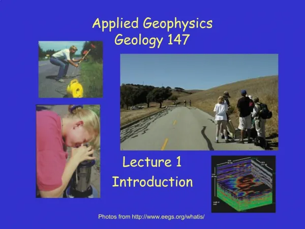
Applied Geophysics
GEOL 492/692. Applied Geophysics 4 credits SP07 call#84362/#87487 Instructor Dr. John Louie, LME 217, ph 784-4219 louie@seismo.unr.edu and GEOL 493/693 Mining Exploration Geophysics 4 credits SP07 call #89118/88005 Instructor Dr. Gary Oppliger, LME 304, ph 784-7056 oppliger@mines.unr.edu


Applied Geophysics
E N D
Presentation Transcript
GEOL 492/692 Applied Geophysics 4 credits SP07 call#84362/#87487Instructor Dr. John Louie, LME 217, ph 784-4219 louie@seismo.unr.edu and GEOL 493/693 Mining Exploration Geophysics 4 credits SP07 call #89118/88005Instructor Dr. Gary Oppliger, LME 304, ph 784-7056 oppliger@mines.unr.edu Office hours: 12:00-1 pm M,T,W
Electrical Properties of RocksandElectrical Resistivity Methods
Resistance • Definition of an OHM • An ohm is a resistance in a conductor that produces a potential differenceof one volt when a current of one ampere is flowing through it. R =
Ohm’s Law http://hyperphysics.phy-astr.gsu.edu/hbase/electric/ohmlaw.html#c1
Resistance vs Resistivity Resistance is relevant only to a particular measurement circuit. Units: Ohms Resistivityis an intrinsic property of all physical materials Units: Ohm-Meters Apparent Resistivity is a resistivity estimate based on a assuming a half-space geometry. Units: Ohm-meters
Electrical Resistivity vs Electrical Conductivity Resistance =ρ (ohm-meters) Conductivity = σ = 1/ρ (mho/meters)
Calculating Resistance from Resistivity • http://www.cflhd.gov:80/agm/index.htm
Factors Influencing Electrical Conductivity in Rocks Porosity(connected/effective - fractures or pores) Pore saturation (% air or gas) Hydrocarbon Fluid Saturation Water salinity (TDS) Clay Content Metallic Sulfide Mineral Content Fluid temperature Rock Matrix intrinsic resistivity
The conductivity of most geological formations can be fit to Archie’s Law
Influence of Permeability A rock with a non-conducting matrix must be permeable (connected pores) as well as porous to conduct electricity. Darcy's Law: Ohm's Law: where Despite the similarity between Darcy’s and Ohm’s Laws, electric currents have zero viscosity so even a narrow crack can provide an effective electrical connection between pores that not contribute to hydraulic permeability.
Comparison of electric and hydraulic properties. • http://www.cflhd.gov:80/agm/index.htm
Metallic Sulfide Mineral Content Electrical resistivity of rocks with various wt % of sulfide. • http://www.cflhd.gov:80/agm/index.htm
Effect of Water Temperature http://appliedgeophysics.berkeley.edu:7057/dc/figures/fig43_7.jpg
Conductivity Ranges of Various Materials http://www.cflhd.gov:80/agm/index.htm
Resistance vs Resistivity Resistance is relevant only to a particular measurement circuit. Units: Ohms Resistivityis an intrinsic property of all physical materials Units: Ohm-Meters Apparent Resistivity is a resistivity estimate based on a assuming a half-space geometry. Units: Ohm-meters
Calculating Resistance from Resistivity • http://www.cflhd.gov:80/agm/index.htm
current I C2 C1 P1 P2 Four Electrode Resistivity Measurement on rock sample … are used to avoid electrode contact resistance effects seen in two electrode measurements.
Four electrode resistivity arrays http://www.cflhd.gov/agm/images/fig90.jpg
The Basic Concept of an Earth Resistivity Measurement http://www.cflhd.gov/agm/images/fig91.jpg
Fig. 5.4g Electrode Contact Resistance is typically much higher than the intrinsic earth resistivity
Fig. 5.4g Electrode Contact Resistanceis concentrated around each electrode
Fig. 5.4g If a standard two electrode resistivity meter were used to measure the earth’s “resistance” we only obtain information on the quality of the electrode contacts – not the earth’s resistivity
Pole-Pole Array http://appliedgeophysics.berkeley.edu:7057/dc/em44.pdf
Pole-Dipole Array http://appliedgeophysics.berkeley.edu:7057/dc/em44.pdf
Pole-Dipole Array http://appliedgeophysics.berkeley.edu:7057/dc/em44.pdf
Wenner Array http://appliedgeophysics.berkeley.edu:7057/dc/em44.pdf
Schlumberger http://appliedgeophysics.berkeley.edu:7057/dc/em44.pdf
Fig. 5.4g The electric potential varies as 1/r around a single current electrode on a homogeneous half-space
Fig. 5.6g Equal potential voltage surfaces between the electrodes