Download
1 / 38
380 likes | 586 Vues
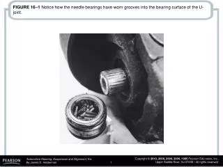
FIGURE 16–1 Notice how the needle bearings have worn grooves into the bearing surface of the U-joint. FIGURE 16–2 All U-joints and spline collars equipped with a grease fitting should be greased four times a year as part of a regular lubrication service. (Courtesy of Dana Corporation).

E N D
FIGURE 16–1 Notice how the needle bearings have worn grooves into the bearing surface of the U-joint.
FIGURE 16–2 All U-joints and spline collars equipped with a grease fitting should be greased four times a year as part of a regular lubrication service. (Courtesy of Dana Corporation)
FIGURE 16–3 Many U-joints require a special grease gun tool to reach the grease fittings. (Courtesy of Dana Corporation)
FIGURE 16–4 Always mark the original location of U-joints before disassembly.
FIGURE 16–5 Two types of retaining methods that are commonly used at the rear U-joint at the differential. (Courtesy of Dana Corporation)
FIGURE 16–6 The best way to check any U-joint is to remove the driveshaft from the vehicle and move each joint in all directions. A good U-joint should be free to move without binding. (Courtesy of Dana Corporation)
FIGURE 16–7 Typical U-joint that uses an outside snap ring. This style of joint bolts directly to the companion flange that is attached to the pinion gear in the differential.
FIGURE 16–8 A U-joint that is held together by nylon and usually requires that heat be applied to remove from the yoke.
FIGURE 16–9 Use a vise and two sockets to replace a U-joint. One socket fits over the bearing cup and one fits on the bearing to press fit the cups from the crosspiece.
FIGURE 16–10 Taping the U-joint to prevent the caps from coming off.
FIGURE 16–11 A special tool being used to press apart a U-joint that is retained by injected plastic. Heat from a propane torch may be necessary to soften the plastic to avoid exerting too much force on the U-joint.
FIGURE 16–13 When installing a new U-joint, position the grease fitting on the inboard side (toward the driveshaft tube) and in alignment with the grease fitting of the U-joint at the other end.
FIGURE 16–14 The working angle of most U-joints should be at least 1/2 degree (to permit the needle bearing to rotate in the U-joints) and should not exceed 3 degrees or a vibration can occur in the driveshaft, especially at higher speeds. The difference between the front and rear working angles should be within 1/2 degree of each other.
FIGURE 16–15 An inclinometer with a magnetic base is being used to measure the angle of the driveshaft at the rear U-joint.
FIGURE 16–16 Placing a tapered metal wedge between the rear leaf spring and the rear axle pedestal to correct rear U-joint working angles.
FIGURE 16–17 A transmission oil pan gasket leak allowed automatic transmission fluid (ATF) to saturate the rear transmission mount rubber, causing it to collapse. After replacing the defective mount, proper driveshaft angles were restored and the driveline vibration was corrected.
FIGURE 16–18 The hub nut must be removed before the hub bearing assembly or drive axle shaft can be removed from the vehicle.
FIGURE 16–19 Many knuckles are attached to the ball joint on the lower control arm by a pinch bolt.
FIGURE 16–20 The preferred method for separating the tie rod end from the steering knuckle is to use a puller such as the one shown. A “pickle-fork”-type tool should be used only if the tie rod is going to be replaced. A pickle-fork-type tool can damage or tear the rubber grease boot. Striking the tie rod end with a hammer while holding another hammer behind the joint to shock and break the taper from the steering knuckle can also be used.
FIGURE 16–21 Many drive axles are retained by torque prevailing nuts that must not be reused. Torque prevailing nuts are slightly deformed or contain a plastic insert that holds the nut tight (retains the torque) to the shaft without loosening.
FIGURE 16–22 A special General Motors tool is being used to separate the drive axle shaft from the wheel hub bearing.
FIGURE 16–23 Most inner CV joints can be separated from the transaxle with a prybar.
FIGURE 16–24 When removing a drive axle shaft assembly, use care to avoid pulling the plunge joint apart.
FIGURE 16–25 If other service work requires that just one end of the drive axle shaft be disconnected from the vehicle, be sure that the free end is supported to prevent damage to the protective boots or allowing the joint to separate.
FIGURE 16–26 With a scribe, mark the location of the boots before removal. The replacement boots must be in the same location.
FIGURE 16–27 Most CV joints use a snap ring to retain the joint on the drive axle shaft.
FIGURE 16–28 After releasing the snap ring, most CV joints can be tapped off the shaft using a brass or shot-filled plastic (dead-blow) hammer.
FIGURE 16–29 Typical outer CV joint after removing the boot and the joint from the drive axle shaft. This joint was removed from the vehicle because a torn boot was found. After disassembly and cleaning, this joint was found to be OK and was put back into service. Even though the grease looks terrible, there was enough grease in the joint to provide enough lubrication to prevent any wear from occurring.
FIGURE 16–30 The cage of this Rzeppa-type CV joint is rotated so that one ball at a time can be removed. Some joints require that the technician use a brass punch and a hammer to move the cage.
FIGURE 16–31 Be sure to use all of the grease supplied with the replacement joint or boot kit. Use only the grease supplied and do not use substitute grease.
FIGURE 16–32 A screwdriver is shown, but a punch would be better, to keep the rotor from rotating while removing or installing the drive axle shaft spindle nut.
FIGURE 16–33 The engine had to be raised higher to get the new (noncollapsed) engine mount installed.