Download

1 / 18
180 likes | 362 Vues
Nanoscience and nanotechnology for advanced energy systems. Light Harvesting Catalysis Materials . Two uses of NS and NT for advanced energy systems. Make non-sustainable systems more effective, cleaner, and less expensive ( short-term )

E N D
Nanoscience and nanotechnology for advanced energy systems • Light Harvesting • Catalysis • Materials Two uses of NS and NT for advanced energy systems • Make non-sustainable systems more effective, cleaner, and less expensive (short-term) • Develop more efficient and sustainable energy systems (long-term) NS and NT can impact three broad areas
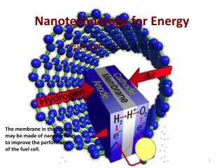
Energy Systems • Energy sources • Energy storage • Energy conversion • Energy use • Emission cleaning
Energy Sources • Non-sustainable sources • Oil • Natural Gas • Coal • Nuclear • Sustainable sources • Photovoltaics (PV) • Solar thermal • Solar hydrogen • Wind • Hydo • Biomass • Geothermal
Impact of NS and NT on Energy Sources • Light Harvesting (LH) • Catalysis (C) • Materials (M)
Impact of NS and NT on Energy Storage • Light Harvesting (LH) • Catalysis (C) • Materials (M)
Impact of NS and NT on Energy Conversion • Light Harvesting (LH) • Catalysis (C) • Materials (M)
Impact of NS and NT on Energy Use and Emission Cleansing • Light Harvesting (LH) • Catalysis (C) • Materials (M)
Materials • Lighter • Improved gas mileage • Stronger • Higher sustainable wind speeds (windmills) • Higher allowable operating temperature • Thermal power generation • Corrosion resistance • Longer service life in aggressive environment (mining, machining, etc.) • Adjustable material properties • Smart windows for efficient heating/cooling Nanoscience enables precise control of materials’ structures, enabling enhanced material properties:
Piezoelectric materials for energy harvesting • Tailored nanostructures of lean zirconate titanate (PZT) with specific dimensions for increased energy scavenging capability Piezoelectric Materials • Enables conversion of mechanical to electrical energy • Electrical polarization upon uniform mechanical stimulus • Harvest the energy from vibration or disturbance originating from footsteps, heartbeats, ambient noise and air flow Dramatic enhancement in energy harvesting for a narrow range of dimensions in piezoelectric nanostructures Physical Review B (Condensed Matter and Materials Physics), v 78, n 12, 15 Sept. 2008, p 121407 Nanowire piezoelectric nanogenerators on plastic substrates as flexible power sources for nanodevices Advanced Materials, v 19, n 1, Jan 8, 2007, p 67-72 • Arrays of piezoelectric, semiconducting ZnO nanowires (NW) grown on flexible plastic substrates can be used to convert mechanical energy into electrical energy using a conductive atomic force microscope
Piezoelectric materials • barium titanate (BaTiO3)—Barium titanate was the first piezoelectric ceramic discovered. • lead titanate (PbTiO3) • lead zirconate titanate (PZT): most commonly used piezo material • potassium niobate (KNbO3) • lithium niobate (LiNbO3) • lithium tantalate (LiTaO3) • sodium tungstate (Na2WO3) • Ba2NaNb5O5 • Pb2KNb5O15 Synthetic Ceramics Crystals - mainly quartz Polymers = Polyvinylidene fluoride (PVDF)
The new field of nanopiezotronics Materials Today, v 10, n 5, May 2007, p 20-8 (a) Scanning electron microscopy (SEM) images of aligned ZnO NWs grown on an a-Al2O3 substrate. (b) Experimental setup for generating electricity through the deformation of a semiconducting and piezoelectric NW using a conductive AFM tip. The root of the NW is grounded and an external load of RL = 500 MW is applied, which is much larger than the inner resistance RI of the NW. The AFM tip is scanned across the NW array in contact mode. (c) Output voltage image obtained when the AFM tip scans across the NW array.
Microfibre–nanowire hybrid structure for energy scavenging Nature 451, 809-813 (14 February 2008) • Simple, low-cost approach that converts low-frequency vibration/friction energy into electricity using piezoelectric zinc oxide nanowires grown radially around textile fibres a, An SEM image of a Kevlar fibre covered with ZnO nanowire arrays along the radial direction. b, Higher magnification SEM image and a cross-section image (inset) of the fibre, showing the distribution of nanowires. c, Diagram showing the cross-sectional structure of the TEOS-enhanced fibre, designed for improved mechanical performance. d, SEM image of a looped fibre, showing the flexibility and strong binding of the nanowire layer. e, Enlarged section of the looped fibre, showing the distribution of the ZnO nanowires at the bending area. ZnO fibers grown using hydrothermal approach
Microfibre–nanowire hybrid structure for energy scavenging - fiber-based generator a, Schematic experimental set-up of the fibre-based nanogenerator. b, An optical micrograph of a pair of entangled fibres, one of which is coated with Au (in darker contrast). c, SEM image at the 'teeth-to-teeth' interface of two fibres covered by nanowires (NWs), with the top one coated with Au. The Au-coated nanowires at the top serve as the conductive 'tips' that deflect/bend the nanowires at the bottom. d, Schematic illustration of the teeth-to-teeth contact between the two fibres covered by nanowires. e, The piezoelectric potential created across nanowires I and II under the pulling of the top fibre by an external force. The side with positive piezoelectric potential does not allow the flow of current owing to the existence of a reverse-biased Schottky barrier. Once the nanowire is pushed to bend far enough to reach the other Au-coated nanowire, electrons in the external circuit will be driven to flow through the uncoated nanowire due to the forward-biased Schottky barrier at the interface. f, When the top fibre is further pulled, the Au-coated nanowires may scrub across the uncoated nanowires. Once the two types of nanowires are in final contact, at the last moment, the interface is a forward biased Schottky, resulting in further output of electric current, as indicated by arrowheads. The output current is the sum of all the contributions from all of the nanowires, while the output voltage is determined by one nanowire.
Heterogeneous Catalysts • Fabrication of catalytic materials with high surface-to-volume ratio • Precise control of size, shape, and chemistry Catalysts save energy by • Reducing operating temperature at which chemical reactions occur • Improve selectivity towards most valuable product Heterogeneous Catalysis - catalyst in different phase than reactants Recent catalyst research High surface area niobium oxides as catalysts for improved hydrogen sorption properties of ball milled MgH2 Journal of Alloys and Compounds, v 460, n 1-2, 28 July 2008, p 507-12 Nanostructured platinum catalyst layer prepared by pulsed electrodeposition for use in PEM fuel cells International Journal of Hydrogen Energy, v 33, n 20, October, 2008, p 5672-5677 Ordered silicon nanocones as a highly efficient platinum catalyst support for direct methanol fuel cells Journal of Power Sources, v 182, n 2, 1 Aug. 2008, p 510-14
"Hairy Foam": Carbon nanofibers grown on solid carbon foam. A fully accessible, high surface area, graphitic catalyst support(Journal of Materials Chemistry, v 18, n 21, , 2008, p 2426-2436) Fig. 7 SEM micrographs of different types of CNF coverage of the RVC after 5 h of CNF synthesis at 773 K using ethylene as the carbon source. Fig. 8 SEM micrographs showing the CNF layer thickness
Planar Model Catalysts Planar model catalysts (PMC): model catalytic systems with specific size and shape, deposited on planar substrates • Easier to model than random structure of “real-life” catalysts allowing for for detailed characterization • Fabrication of catalytic materials with high surface-to-volume ratio • Precise control of size, shape, and chemistry Recent PMC research CO adsorption energy on planar Au/TiO2 model catalysts under catalytically relevant conditions Journal of Catalysis, v 252, n 2, Dec 10, 2007, p 171-177 A novel approach for measuring catalytic activity of planar model catalysts in the polymer electrolyte fuel cell environment Journal of the Electrochemical Society, v 153, n 4, April, 2006, p A724-A730 Carbon monoxide oxidation over well-defined Pt/ZrO2 model catalysts: Bridging the material gap Applied Surface Science, v 253, n 3, 30 Nov. 2006, p 1310-22 Lithographically defined Pt disks
Pd-Alumina PMCs • Low energy electron diffraction (LEED) • Scanning tunnelling microscopy (STM) • Auger electron spectroscopy (AES) • X-ray photoelectron spectroscopy (XPS) The interaction with gas molecules is examined using • Thermal desorption spectroscopy (TDS) • Sum frequency generation (SFG); • Polarization-modulation infrared reflection absorption spectroscopy (PM-IRAS) The model catalysts are characterized with respect to their structure using various techniques: Schematic illustration and STM image of a Pd-Al2O3 model catalyst. Annual Reports on the Progress of Chemistry, Section C (Physical Chemistry), 100 (2004) 237 or Physical Chemistry Chemical Physics, 3 (2001) 4621
Nanoparticle Catalysts Nanoparticle catalysts • Materials can exhibit significantly different reactivity at nanoscale • Bulk gold: inert • Gold nanoparticle: highly active catalyst Novel Fe-Ni nanoparticle catalyst for the production of CO- and CO2-free H2 and carbon nanotubes by dehydrogenation of methane Applied Catalysis A: General, v 351, n 1, Dec 15, 2008, p 102-110 Biodiesel process uses nanoparticle catalyst Industrial Bioprocessing, v 28, n 7, July, 2006, p 2 Au-Ag alloy nanoparticle as catalyst for CO oxidation: Effect of Si/Al ratio of mesoporous support Journal of Catalysis, v 237, n 1, Jan 1, 2006, p 197-206