Nanoscience and Nanotechnology Lecture 19
650 likes | 965 Vues
Nanoscience and Nanotechnology Lecture 19. Only 7 lectures remaining! (including this one) Review of traditional microelectronics Course notes are at: http://www.phys.appstate.edu/nanotech/NanoCourseLecturePPTs2008/. Review of basic semiconductor Physics.

Nanoscience and Nanotechnology Lecture 19
E N D
Presentation Transcript
Nanoscience and NanotechnologyLecture 19 Only 7 lectures remaining! (including this one) Review of traditional microelectronics Course notes are at: http://www.phys.appstate.edu/nanotech/NanoCourseLecturePPTs2008/
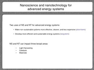
Review of basic semiconductor Physics • When considering the Physics and Engineering of traditional semiconductors, we are mainly concerned with ‘bulk’ properties; and consider surfaces as defects. • This approach is the opposite of the nanotechnology approach, where the goal is to use the special properties of materials and devices at the nm scale, where surface atoms control properties.
Material based on content of: Principles of Electronic Materials and Devices, by S. O. Kasap Third Edition Text WEB site: http://materials.usask.ca/textbook/
Recall the Si band structure
Both electrons and holes can drift in an electric field
Mass action law np=ni2 Mass action law np=ni2 = NcNvexp(-Egap/kT) Where Nc is the density of states near conduction band edge Nv is the density of states near valence band edge
Dopant levels for As impurities (valence V, n-type)) Each as provides an extra loosely bound electron
Band diagram for b doped (p-type) Si Small ionization energy allows thermal ionization at room temperature
Band diagram for b doped (p-type) Si Dopants are far apart Note that the electron from the valance band becomes fixed charge (in energy and position) Small ionization energy allows thermal ionization at room temperature
For an n-type semiconductor (e.g. Arsenic doped) only the electrons are mobile. The ionized dopant atoms do not move. Thus we have added both ‘mobile” and ‘fixed’ or ‘localized’ charge!
For the Case of an extrinsic (doped) semiconductor: we have both ‘mobile’ and ‘fixed’ or ‘localized’ charge! this is a very Important Concept!!! Fixed charge: the ionized dopant atoms Mobile charge: the extra electron or hole contributed by ionization
Temperature dependency of conductivity: critical concept! From this data we can measure: Band gap energy Egap, and Dopant ionization energy DEionization
Conductivity of a Semiconductor = ene + eph • = conductivity, e = electronic charge, n = electron concentration in the CB, e = electron drift mobility, p = hole concentration in the VB, h = hole drift mobility Note: this expression is valid for both intrinsic and extrinsic semiconductors! We now see that n≠p for extrinsic semiconductors.
We can determine n and p (the electron and hole concentrations) if we know g(E) and f(E) and… (The intrinsic case is shown here.)
Mass action law np=ni2: in equilibrium Valid for both intrinsic and extrinsic semiconductors! Mass action law np=ni2 = NcNvexp(-Egap/kT) Where Nc is the density of states near conduction band edge Nv is the density of states near valence band edge If more electrons are added by doping, then fewer holes will exist due to recombination, keeping the product np constant!
Carrier recombination In addition to carrier creation, we will have carrier recombination, i.e. if an electron excited to the CB is located (spatially) near a hole in the VB, the electron will reduce its energy by filling the hole (allowed electron state). The electron and hole annihilate each other (as free charge carriers) via recombination.
CarrierRecombination The recombination rate R will be proportional to both the electron and hole concentrations (and hence to their product) Rnp What about the carrier generation rate G? G will depend on the number of electrons available for excitation at Ev i.e. Nv and empty states at Ec i.e.Nc. And the probability of an electron making the transition i.e. exp[-Eg/kT] so: G NvNc exp[-Eg/kT] In equilibrium G = R, generation and recombination rates are equal. (more on this later) Next: Where is Ef within the band gap?
Table 5.1Selected typical properties of Ge, Si and GaAs at 300 K. Effective mass related to conductivity (labeled a) is different than that for density of states (labeled b). Use effective mass related to conductivity, rather than for density of states.
The combined temperature effects of carrier creation and carrier scattering. KEY CONCEPT!!
Non-degenerate semiconductors (the normal case) We have been assuming that there are many more empty states than there are electrons in the conduction band, and/or many more filled states than holes in the valence band; i.e. that Boltzmann statistics rather than Fermi-Dirac apply. This is the non-degenerate semiconductor case; i.e when n<<Nc and p<<Nv What is the other possibility? Degeneracy! Occurs when doping concentration is very large; usually 1019 or 1020 cm-3 (out of 1023 cm-3)
What happens with very high doping?: Degeneracy Degenerate semiconductors behave as metals; this is very useful!
Si is not direct gap! This is most important in optoelectronic applications (laser, LED, photo…) More on this later.
In this caseEemission is less than Egap Cases where midgap states exist (due to impurities and/or defects) Be sure you understand that midgap states can act as Trap sites or Recombination sites
How can there be allowed states in the forbidden gap? Allowed states (such as the charge carrier trap states and recombination centers of figure 5.23) are localized states within the forbidden band gap energy range of a defect-free material. The states are created by the perturbation of the normal periodic lattice by a point (or other) defect. The trap states are localized in spaceto the area of the defect, and in energy to a specific energy within the band gap; determined by the type of defect creating the state. Examples of defects creating midgap states include vacancies, interstitial and substitutional impurities, dislocations, stacking faults, etc.
How can there be allowed states in the forbidden gap? These allowed individual states created by the perturbation of the normal periodic lattice act as: Recombination sites if near midgap, Or as Trapping sites for electrons if near the CB edge, Or as Trapping sites for holes if near the CB edge. Note that trapping just removes the charge carrier from the free carrier pool for a brief time; with the overall effect of having many traps being a reduction in charge carrier density available for conduction at any given time.
Charge carrier pair is lost permanently due to recombination. Trapping causes a temporary loss of a single charge carrier. Note: phonon assistance is usually required!
How long do free carriers exist? How long do free carriers exist before being trapped or recombined? This depends on the number of traps and recombination centers; which depends on the number (actually density) of defects. If we measure carrier lifetime, we get an idea of the perfection of the semiconductor: which is very useful in developing processing. How can we measure carrier lifetime?
Carrier creation: Photoinjected charge carriers If we shine light on a semiconductor, we will generate new charge carriers (in addition to those thermally generated) if Ephoton>Egap. If the light is always on and of constant intensity, some steady state concentration of electrons and holes will result.
Carrier creation: Photoinjected charge carriers Let’s consider the case of n-type material Consider an n-type semiconductor with a doping concentration of 5 x 1016 cm-3. What are the carrier concentrations? Let’s define some terms; nno majority carrier concentration in the n-type semiconductor in the dark(only thermally ionized carriers) (i.e. the electron concentration in n-type) pno minority carrier concentration in the n-type semiconductor in the dark(only thermally ionized carriers) (i.e. the hole concentration in n-type) Note: the no subscript implies that mass action law is valid!
When we have light: With light of Ephoton>Egap hitting the semiconductor, we get photogeneration of excess charge carriers. nn excess electron concentration such that:: nn = nn-nn0 And pn excess hole concentration such that:: pn = pn-pn0 Note that photogenerated carriers excited across the gap can only be created in pairs i.e. pn = nn and now (in light) nnpn≠ni2i.e. mass action not valid!
Carrier density change under illumination If the temperature is constant, nn0 and pn0 are not time dependent, so and Consider the case of ‘weak’ illumination, which creates a 10% change in nn0 i.e. nn = 0.1nn0 Or if the doping level is nno=5 x 1016cm-3, then nn = 0.1nn0= 0.5 x 1016cm-3 And pn =nn = 0.5 x 1016cm-3 Which change is more important? Majority or minority?
Recall the intrinsic carrier concentration For Si ni is roughly 1.5x1010cm-3 At room temperature Since pno=ni2/nn0 = (1.5x10¹⁰)2/5x1016 pno =4500 cm-3
pn =nn = 0.5 x 1016cm-3 An extremely important concept! Minority carrier concentration can be controlled over many orders of magnitude with only a small change in majority concn.
Carrier creation followed by recombination Almost equal Carrier concns In light The extra minority carriers recombine once the generation source is removed. Mostly majority carriers in the dark How quickly do the carriers recombine?
Minority carrier lifetime h for n-type h = average time a hole exists in the valance band from its generation until its recombination And so 1/ h is the average probability (per unit time) that a hole will recombine with an electron. h depends on impurities, defects and temperature. The recombination process in a real semiconductor usually involves a carrier being localized at a recombination center. • can be short (nanoseconds) allowing fast response (e.g. switch) or slow (seconds) for a photoconductor or solar cell
Excess Minority Carrier Concentration pn = excess hole (minority carrier) concentration, t = time, Gph = rate of photogeneration, h = minority carrier lifetime (mean recombination time) h = average time a hole exists in the valance band from its generation until its recombination
Carrier concentration versus time with pulsed illumination t’ is time after illumination is removed
Continuous illumination provides increased conductivity Often used as a switch or motion detector
Carrier motion in a concentration gradient How can we describe how charge carriers move is response to a concentration gradient? It is just simple diffusion; i.e Ficks first law; but of course it is with charged ‘particles’ Diffusion current density = (charge) x flux Where Flux = N/A t or #of charge carriers passing unit area per unit time Ficks first law relates flux to concentration gradient Flux =e= -De dn/dx for electrons Where De = diffusion coefficient for electrons