Advanced SRF Cavity Designs for the International Linear Collider: Electromagnetic Modeling Insights
10 likes | 136 Vues
This paper presents the advancements in the design of superconducting radio frequency (SRF) cavities for the International Linear Collider (ILC) through high-fidelity electromagnetic modeling. Utilizing cutting-edge tools from the US DOE SciDAC program, including finite element codes like Omega3P and Track3P, we analyze various cavity designs. Key findings address issues such as cell deformation impacts on frequency split and cavity performance. Results from baseline, low-loss, and deflecting cavity designs are discussed, informing the future of ILC cavity development.

Advanced SRF Cavity Designs for the International Linear Collider: Electromagnetic Modeling Insights
E N D
Presentation Transcript
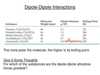
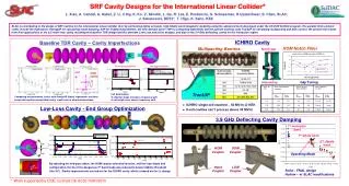
Notch gap split Ideal cavity Cell elliptical distortion Cell length distortion scatter shift Antenna tip 5.0 400 450 SRF Cavity Designs for the International Linear Collider* L. Xiao,A. Candel, A. Kabel,Z. Li, C.Ng, K. Ko, V. Akcelik, L. Ge, R. Lee,E. Prudencio, G. Schussman, R.Uplenchwar, S. Chen, SLAC; J. Sekutowicz, DESY; T. Higo, K. Saito, KEK SLAC is contributing to the design of SRF cavities for the International Linear Collider (ILC) by performing highly accurate, high fidelity electromagnetic modeling using the advanced tools developed under the US DOE SciDAC program. The parallel finite element codes include the eigensolver Omega3P for calculating mode damping, S3P for finding S-parameters, the time-domain solver T3P for computing wakefields and the particle tracking code Track3P for simulating multipacting and dark current. We present the results from their applications to the ILC main linac cavity including the baseline TDR design and the alternate Low-Loss and Ichiro designs, and also to the 3.9 GHz deflecting cavity for the interaction region. Baseline TDR Cavity – Cavity Imperfections ICHIRO Cavity HOM Notch Filter Multipacting Barriers 1 Gap Tuning dr=0.25mm Track3P Cell deformation: • elliptical shape increases frequency split • cell length error causes frequency shift. Comparing measurements (color) with Omega3P (black) eigenmode solutions shows data scatter around ideal cavity results due to shape deformations • ICHIRO single cell reached ~ 50 MV/m @ KEK • 9-cell cavities can’t process above 30 MV/m Low-Loss Cavity - End Group Optimization 3.9 GHz Deflecting Cavity Damping 1st monopole band 1st dipole band 2nd dipole band HOM Coupler SOM Coupler Operating Mode By adjusting the end-pipe radius, the HOM coupler azimuthal location, and the loop shape and configuration, the Qe of the dangerous 3rd band mode was reduced to below stability threshold (Qe<105). Similar improvements carried out for the ICHIRO cavity which is based on the LL design. Input Coupler LOM Coupler Solid – FNAL design Hollow – w/ SLAC modifications * Work supported by DOE contract DE-AC02-76SF00515