Elliptical Dipole
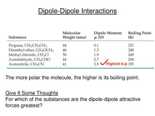
Elliptical Dipole. Motivation. Bending magnets in muon collider: exposed to decay particles a few kW/m from short lived muons Distribution is highly anisotropic large peak at the midplane ( Mokhov ) One suggestion: open midplane dipoles Issue: filed quality.

Elliptical Dipole
E N D
Presentation Transcript
Motivation • Bending magnets in muon collider: • exposed to decay particles • a few kW/m • from short lived muons • Distribution is highly anisotropic • large peak at the midplane (Mokhov) • One suggestion: open midplane dipoles • Issue: filed quality Nikolai Mokhov, in “Brief Overview of the Collider Ring Magnets Mini-Workshop, Telluride 2011.
Task Inside pipe width = 5 cm Inside pipe height = 2 cm Tungsten liner From: Suggested shield & cos theta dipole dimensions R. B. Palmer, 5/26/11
Methodology developed for Integrable Optics Lattice (FNAL) • Task: generate certain vector potential • Singularities • Difficult to approximate with multipole fields • Ideally non-circular aperture – 2 cm horizontal, 4 cm vertical
Vector Potential of Single Line Current • Vector potential at point P due to current I (in z-direction): • Magnetic field: y P R r I a x
Methodology • Required: desired Az and coil bore • A~I, therefore: • P2: • Generally: I1 P2 P1 Beam Aperture A11=VP @ P1 for unit current I1 A21=VP @ P2for unit current I1 A12=VP @ P1 for unit current I2
Methodology: Formalism • Same is true for multiple currents and positions P • Formalism: • Linear equation system: Ax=b I4 I3 I3 I2 I1 P2 P1 P3 P3 P4 A11, A12, ... are known (can be calculated – unit current Im, calculate Az at Pn) b: also known (this is the vector potential we want) A · x = b
Example: Quadrupole Current
Rectangular Shape Reference Az Conductor
From 2D to 3D • Power each current strand individually • Very inefficient, clumsy • Not very elegant • Known current distribution • Helical coil: vector addition of two currents, which always intersect at the correct angle Vector addition
From 2D to 3D • Easy if functional relationship is known (i.e. cos theta) • Here: • (x,y) position knownneed to determine z • dz=dI In+1 In In-1 ds
Quadrupole Calculated for two coils
Task Inside pipe width = 5 cm Inside pipe height = 2 cm From: Suggested shield & cos theta dipole dimensions R. B. Palmer, 5/26/11
Concept: Elliptical Helical Coil Task: Find 2D current distribution which generates (almost) pure dipole field Calculate this for a set of positions on ellipse A-axis: 9.1 cm /2 B-axis: 13.77 cm /2 y (m) x (m)
Answer: Current Distribution Normalized current density vs. azimuthal angle
Implementation: Elliptical Helical Coil 40 turns Spacing: 20 mm (= length about 0.8 m + “coil ends”) Single double layer Current in strand: 10 kA (=400 kA turns) Average current density: 10 kA/(20mmx1 mm)=500A/mm2
Field Harmonics Normalized to Dipole field of 1T Evaluated for radius of 25 mm Well behaved: small sextupole component at coil entrance and exit
Field along z 10 kA = 1.1T B (T) z (m) All unwanted field components point symmetric to the origin should disappear (e.g. Bz) for 4-layer arrangement
Other Geometries? • Well-known: intersecting ellipses produce dipole field • Worse performance • Field quality • Peak field on wire • Less flexible • Coil end problem? • Geometry problem • Approximation with blocks • Stresses? J+ J-
Integrable Optics • Introduce tune shift to prevent instabilities • Introduces Landau damping • One option for high intensity machines • Key: Non-linear block • Length 3 m 13 m Nonlinear Lens Block 10 cm 5.26 F F
Required Vector Potential • Singularities • Difficult to approximate with multipole fields • Ideally non-circular aperture – 2 cm horizontal, 4 cm vertical
Quadrupole Gauging
Gauging • Circular coil: constant current in longitudinal direction will cause a uniform vector potential A0 within this circle • Az(x,y)=A1(x,y)+A0 • N.b.: • Ergo: changes vector potential but not field • Allows to shift current
Gauging for elliptical coils • For elliptical coils (or other shapes): some modest variation of Az • Example: quadrupole • Correction per current strand: 2kA • Field: 0.3 mT
Methodology • Required: desired vector potential • Defined by application • Required: beam aperture • Defined by application • (Real coil will be slightly larger) Az y x Beam Aperture
Methodology (cont.) • Define point P1 on desired cross-section (known Az) • Define current I1 (for example on coil cross-section) • Az can be calculated from I1 P1