Download
1 / 36
360 likes | 382 Vues
This presentation discusses the challenges faced in the PIP-II Linac, including low beam loading, low efficiency, and microphonics issues. The talk also explores the solutions and control strategies for these problems.

E N D
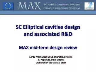
SlavaYakovlev 4th SLHiPPMeeting May 15-16, 2014 Fermilab elliptical cavities
PIP-II Linac : • Low beam loading; • Long filling time compared to pulse length; • Low efficiency at pulse mode. SLHiPP-4, May 2014; Slava Yakovlev
PIP II SRF Linac Technology Map *3-cavity option is under consideration; CM has no focusing elements. SLHiPP-4, May 2014; Slava Yakovlev
Accelerating cavity types and characteristics for the SC linac. • Epeak≤ 40 MV/m, for CW (Field emission); • Bpeak≤ 75 mT, for CW (medium field Q-slope) SLHiPP-4, May 2014; Slava Yakovlev
PIP II cavity Issues: CW option high Q0 Low beam loading microphonics, LFD (pulse regime) HOMs “to damp or not to damp?” Input coupler issues Design issues: low EM fields aperture choice cavity shape trapped modes MP SLHiPP-4, May 2014; Slava Yakovlev
Single Cell Cavity Tests: Nitrogen Treatment during vacuum bake LCLS-II *A.Grassellinoet al, 2013 Supercond. Sci. Technol. 26 102001 <Q0>(FG) = 4.2e10* Surface doping: baseline strategy to improve RBCS and allow high Q for LCLS-II at 2K Current R&D Goal: Develop a robust surface processing recipe based on Nitrogen Treatment for LCLS-II Spec Q>2.7e10 at 2K, 1.3 GHz, 16 MeV/m • and transfer to industry SLHiPP-4, May 2014; Slava Yakovlev
Typical bake cycle – small deviation from standard XFEL degassing cycle* Gas injection, ~10 min Standard 800C degassing cycle *A Grassellino et al 2013 Supercond. Sci. Technol.26 102001 SLHiPP-4, May 2014; Slava Yakovlev
New FNAL discovery: cooling details matter for bare cavities example for nitrogen doped ~1.8K/min trough Tc ~0.3 K/min trough Tc *A. Romanenko et al, J. Appl. Phys. 115, 184903 (2014) SLHiPP-4, May 2014; Slava Yakovlev
Nine cell TB9ACC015 – world record Q nine cell at mid Eacc T=2K f=1.3GHz Q LCLS-II spec E [MV/m] SLHiPP-4, May 2014; Slava Yakovlev
Nine cells N doped vs typical 120C bake: comparison at 2K, mid field: 2-3 times higher Q Q Eacc [MV/m] SLHiPP-4, May 2014; Slava Yakovlev
High-Order Modes in Project X cavities • HOM damper is a vulnerable, expensive and complicated part of SC acceleration structure (problems – multipactor, heating, damage of feed-through, etc; additional hardware – cables, feed-through, connectors, loads); • Specifics of Higher Order Mode effects in the PIP II pulsed/CW Linac: • Non-relativistic beam; • Small current and small bunch population; • No feedback (linac); • Complicated beam timing structure • (dense frequency spectrum). • Possible issues: • Resonance excitation of HOMs; • Collective effects; • Cryo-losses; • Emittance dilution (longitudinal and transverse). SLHiPP-4, May 2014; Slava Yakovlev
Scope of HOM investigations: • Loss factor calculations for non-relativistic beam; • Beam spectrum investigation for different Project X operation options; • Cavity spectrum investigations (simulations and measurements) for all the PIP II sections - HWR, SSR1, SSR2, LB650 and HB650 – impedance and spectrum density versus frequency; • Resonant frequency spread for HOMs estimations and if possible measurements for all the cavities of the PIP II; • Q estimations for different modes; • HOM impedance spread (estimations and measurements) for all the cavities of the Project X; • HOM impedance dependence on the particle velocity over the linac; • Microphonics for different HOMs; • Stability of HOMs versus operation mode tuning/detuning; • Cryogenic loss estimations for different option of the Project X operation (taking into account propagating and non-propagating modes); • Estimation of the beam emittance (longitudinal and transverse) dilution caused by HOMs; • Longitudinal “klystron type” instabilities caused by HOMs; • Transverse instability – BBU; • Comparison to operating accelerators (SNS) SLHiPP-4, May 2014; Slava Yakovlev
Studies of HOMs in the PX: • “to damp or not to damp?” Detailed simulations show: • Beam Break Up (BBU) should not be a problem; • “Klystron-type” longitudinal instability does not look to be a problem as well. • Resonance excitation of the dipole modes does not look to be an issue; • Accidental resonance excitation of the 2d monopole band in beta=0.9 section may lead to longitudinal emittance dilution, but probability is very small. However, v.2of the cavity was designed which is free of this issue. No HOM dampers! SLHiPP-4, May 2014; Slava Yakovlev
Microphonics in PIP II Cavities Low beam loading (1-2 mA) → narrow cavity bandwidth → microphonics issues. • Microphonics Control Strategies: • Providing sufficient reserve RF power to compensate for the expected peak detuning levels. • Improving the regulation of the bath pressure to minimize the magnitude of cyclic variations and transients. • Reducing the sensitivity of the cavity resonant frequency to variations in the helium bath pressure (df/dP). • Minimizing the acoustic energy transmitted to the cavity by external vibration sources. • Actively damping cavity vibrations using a fast mechanical or electromagnetic tuner driven by feedback from measurements of the cavity resonant frequency. SLHiPP-4, May 2014; Slava Yakovlev
He vessel and tuner design for 650 MHz cavity Blade Tuner – scaled ILC: • High df/dP, • Insufficient tuning efficiency; • New End Tuner design: • Low df/dP, • Mechanical resonance s > 60 Hz; • Good tunability; • Less expensive. Stiffening rings located to minimize df/dP while maintaining tunability SLHiPP-4, May 2014; Slava Yakovlev
Requirements to Project X RF couplers Cavity SSR1 (325MHz): Max. energy gain - 2MeV, Max. power , 1 mA case* - 4 kW, Max. power , 2 mA case* -6 kW Cavity SSR2 (325MHz): Max. energy gain- 5.3 MeV Max. power ,1 mA case* - 12 kW, Max. power , 2 mA case* - 17kW 325 MHz coupler has to provide reliable operation at power level of ~ 30 kW, CW, taking into account possible operation at higher current in future. Cavity HB650 (650MHz): Max. energy gain - 17.7 MV, Max. power , 1 mA case* - 30 kW, Max. power , 2 mA case* -50 kW Cavity LB 650 (650MHz): Max. energy gain - 11.7 MV, Max. power , 1 mA case* - 30 kW, Max. power , 2 mA case* -40 kW 650 MHz coupler has to provide reliable operation at power level of ~ 100 kW, CW. * Taking into account overhead (losses, control, microphonics). SLHiPP-4, May 2014; Slava Yakovlev
650 MHz, 120 kW CW coupler: • One window; • Air cooling; • Non-adjustable; • Bias is possible. • 325 MHz coupler prototype: • Three couplers are manufactured, measured (reflection -22 dB at 325 MHz) and will be tested in few weeks. • The test stand is ready SLHiPP-4, May 2014; Slava Yakovlev
Cavity design: working assumptions: • Surface fields. • Field enhancement factors should be as small as possible in order to provide higher gradient. • Bpk≤ 70 mT, Epk ≤ 40 MV/m. • Coupling coefficient k: • Smaller k → smaller field enhancement factors; • Limitation: • field flatness: • δE/E ~ fπ /|fπ-fπ(N-1)/N| ≡ fπ /δf ≈ 1/kN2→ k~1/N2. • For ILC, N=9: δf /fπ = 6e-4 (k=1.87%); • We use, N=5: δf /fπ = 8e-4 (k=0.75%). SLHiPP-4, May 2014; Slava Yakovlev
Aperture: • Smaller aperture → smaller field enhancement factors; • Limitations: • beam losses, • field flatness, • mechanical stability, • surface processing. • SNS (805 MHz): 2a=86mm (β=0.61), 2a/λ = 0.23 • 2a=98mm (β=0.81), 2a/λ = 0.26 • HIPPI (704 MHz): 2a=80mm (β=0.47), 2a/λ = 0.19 • We use (650 MHz): 2a=83mm (β=0.61), 2a/λ = 0.18 (FNAL) • 2a=100mm (β=0.61), 2a/λ = 0.22 (JLAB) • 2a=100 mm (β=0.9), 2a/λ = 0.22 (v.1) • 2a=118 mm (β=0.9), 2a/λ = 0.26 (v.2) SLHiPP-4, May 2014; Slava Yakovlev
Cavity wall slope: • Smaller slope → smaller field enhancement factor; • Limitations : • mechanical stability, • surface processing. • We use: • 5 deg for β=0.9 (compared to 7 deg for ILC); • 2 deg for β=0.61 (LL has zero slope, Re-entrant has negative). • Should be no trapped modes (optimization of the end cells); • Mechanical stability – under consideration. • Very first impression: β=0.9 is OK, • β=0.61 may need revision. SLHiPP-4, May 2014; Slava Yakovlev
650 MHz, 5-cell cavities High-beta Low-beta SLHiPP-4, May 2014; Slava Yakovlev
LB/ HB 650 • EM design of both LB and HB 650 is ready. • Two singe-cell LB 650 cavities are manufactured, processed and tested (JLAB); • Six single-cell cavities HB 650 are manufactured by AES, processed and tested at Fermilab. • Two HB 650 cavities are processed and tested. • Four 5-cell HB 650 cavities are manufactured by AES and ready for processing and tests. • Five additional single cell and five five-cells HB cavities ordered from industry (PAVAC) on ARRA funds • Design of He vessel for HB 650 with low df/dP and the tuners (slow and fast) are completed. • Concept design of the CM for HB 650 is ready. SLHiPP-4, May 2014; Slava Yakovlev
JLAB version of the 650 MHz, beta=0.61 cavity for the PIP II For the cavity #2 Q0 >4e10 @17MeV/m SLHiPP-4, May 2014; Slava Yakovlev
650 HB MHz cavities Currently Available Cavities: Expected Cavities: 1-Cell 650 MHz 1. B9AS-AES-001* 2. B9AS-AES-002* 3. B9AS-AES-003 4. B9AS-AES-004 5. B9AS-AES-005 6. B9AS-AES-006 5-Cell 650 MHz 1. B9A-AES-007 2. B9A-AES-008 3. B9A-AES-009 4. B9A-AES-010 1-Cell 650 MHz Pavac, Inc. Six to be delivered late spring 2014. 5-Cell 650 MHz Pavac, Inc. Five to be delivered early summer 2014. *VTS Tested SLHiPP-4, May 2014; Slava Yakovlev
650 MHz testing/processing infrastructure SLHiPP-4, May 2014; Slava Yakovlev 120-300C ovens--ready High temperature furnace -- ready EP, HPR tools, ready for 1-cell, not for 5-cell 650 MHz VTS1—ready for 1-cell 650 MHz VTS2,3—not commissioned, needed for 5-cell 650 MHz
Surface processing studies • Explored several different surface processing techniques on 650 MHz single cells • All cases largely exceed the PIP-II specs of Q ~ 2e10 at 17 MV/m SLHiPP-4, May 2014; Slava Yakovlev
650 MHz 5-cell Infrastructure Prep SLHiPP-4, May 2014; Slava Yakovlev EP tool at ANL—new cathode required plus tool testing and evaluation. External cooling implemented. HPR—requires adapters to accommodate multi-cell cavities. Transport tooling—requires adapters to accommodate multi-cell cavities. 4-bar frames—designed, need to be procured. VTS hardware—several sets in-hand. More to be ordered including new RF feethroughs.
650 MHz Testing Plan 2014 SLHiPP-4, May 2014; Slava Yakovlev 2-3 AES 1-cell cavity tests. High Q0 studies in VTS. 2-3 AES 5-cell cavities for baseline processing after VTS2-3 are ready and HPR/cleanroom infrastructure procured. Vendor qualification. 2-3 Pavac single-cell cavities for vendor qualification purposes. 2 Pavac multi-cell cavities for vendor qualification.
650 MHz Cryomodule. (6 cavities, β=0.9, DESY Style, stand alone) -Heat Exchanger -Cryogenic stuff: bayonets connections (He supply and return), Cryogenic valve control system -End plates (2) -Power couplers (6) -CM support (1-fix, 2-sld) -Vacuum Vessel (pipe: 48”-OD, .375”-wall) -Beam pipe -Ports for access to Tunermotors (6) SLHiPP-4, May 2014; Slava Yakovlev
650MHz Cryomodule Layout(6 cavities, β=0.9, DESY Style-SA) • Overall length (CS-Flange to Flange) ~9480mm • Number of Cavitis-6 • Distance between couplers-1468.9mm • Interconnection bellows length ~135.3mm • Beam pipe ID-100mm • 1-RF all metal GV for each end of Beam Pipe (cold) • Number of Support posts-3 • 300mmpipe (concept) serves as strong back, as the 2-phase helium pipe, also providing a large vapor buffer volume. • Heat exchanger • Insulation Vacuum Relief valve SLHiPP-4, May 2014; Slava Yakovlev
650 MHz Cavity, β=0.9. String version with strong back He reservoir with level sensor 650 Cavity with 2-phase pipe Warm up cool down pipe Strong back (Tray) with 2 supports for each cavity 5K circuit (to MC) 70K circuit (shield) Used scheme of SSR1, by T. Nicol PIP-II MAC, V. Yakovlev 31 SLHiPP-4, May 2014; Slava Yakovlev
650 MHz 3-cavity Cryomodule, β=0.61. SSR1 & DESY Style (stand alone) • Overall length (CS-Flange to Flange)~4200mm • Number of Cavitis-3 (shorter approx. 300mm) • Distance between couplers-1468.9mm • Interconnection bellows length-135.3mm • Gate valve (cold) for each end of Beam Pipe (2) • Number of Support posts-2(1-Fix, 2-Sliding) or 6 (SSR1) • Cavity string support: 300mm pipe serves as strong back, as the 2-phase • helium pipe (DESY St.), or strong back (SSR1 St.) SLHiPP-4, May 2014; Slava Yakovlev
650 MHz Cryomodule, β=0.61. (SSR1 Style, stand alone)-3 cavity concept Heat Exchanger Cryogenic stuff: bayonets connections (He supply and return), Cryogenic valve control system Power couplers (3) Beam pipe Vacuum Vessel (pipe: 48”-OD, .375”-wall) SLHiPP-4, May 2014; Slava Yakovlev
650 MHz Cryomodule, β=0.61. Cold Mass (SSR1 Style)-3 cavity concept -650 MHz, β=0.61, cavity with lever tuner (not shown) -Cavity Bearing supports -2-phase pipe (ID= 16.3cm) -He level -Gate valve -Strong Back -Cryogenic piping -Cavity alignment supports -Support posts (2 per cavity) SLHiPP-4, May 2014; Slava Yakovlev
PIP II Cavity and CM development SLHiPP-4, May 2014; Slava Yakovlev
Conclusions • Design of the cavities, input couplers and cryo-modules for all the sections of the PIP IIlinac • - SSR1; • - SSR2; • - LB650; • - HB650 • is in progress; • Investigations of HOM influence on the accelerator • operation are completed; • “High Q0 program” is developing; • Microphonics and LFD investigations are in progress. SLHiPP-4, May 2014; Slava Yakovlev