Download
1 / 29
300 likes | 494 Vues
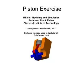
2- Crankshaft, Piston Pin, and Piston Rod Bushing. Basic Pipsqueak engine.

E N D
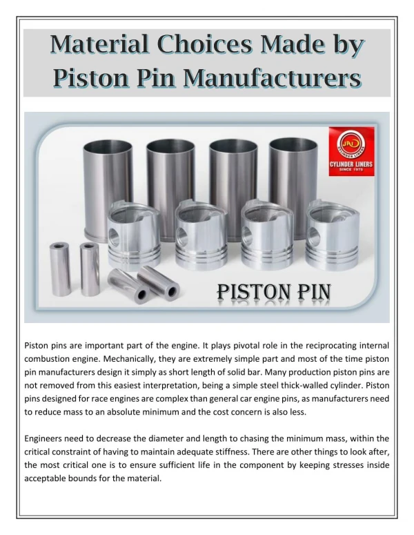
Basic Pipsqueak engine Recognize machined surfaces that are purely for appearance. Also recognize mechanical connections, fits and alignments that are critical for function. Tolerances on your drawings are intended to provide adequate control of these features to assure proper function.
#8-32 X 3/16” set screw #10-24 X 3/8” oval head screw #6-32 X ½” Pan head screw #10-32 brass barbed fitting #10-32 X ½” Flat Head Screws ¼” O.D. X 1/16” wall PVC tubing 10-32 flat head screws 3/8” O.D. X .028 wire dia. X ¾” Spring Pipsqueak engine hardware available in Projects Lab 7/16” O.D. X 5/16” I.D. X ½” long bronze bushings
Press fits, or interference fits are sometimes used in manufacturing to reduce manufacturing costs or liabilities. There are however disadvantages to using this assembly method. Precise sizing procedures are necessary to get the correct fit. Generally, precision fixtures are necessary to consistently align the parts while they are assembled. Excessive assembly force can distort parts or their alignment. The option for disassembly for adjustment or additional unforeseen finishing processes is eliminated. • An alternate method of assembling pipsqueak parts using screw threads is easier to accomplish and disassembly is a simple option.
Threaded assembly option Crank shaft to crank wheel, piston rod bushing to crank wheel and pivot shaft to cylinder are good candidates for screw thread assembly.
Flywheel Connection The flywheel can also be connected with screw threads.
Flywheel secured to the crankshaft with a set screw Or the Flywheel can be secured to the crankshaft with a set screw. This is the more common method of securing a low torque component to a shaft. It works well with the geometry of this flywheel.
Crankshaft setup in vise For the set screw option, mill a spot face on the crankshaft for flywheel set screw to seat against. This prevents the set screw from making a burr on crankshaft O.D., which makes dis-assembly difficult. The spot face also serves as a positioning feature.
Screw thread option To use the screw thread option, first face the shaft to finish length. This gives a good flat surface for the mating part to seat against. It is not necessary to face the shaft near the center of the shaft where a hole will be drilled.
Center Drilling Center drill shaft to a diameter slightly larger than the nominal thread size. This will leave a desirable chamfer on the threaded hole. Use appropriate cutting speed and cutting fluid.
Drilling with a tap drill Drill with correct tap drill (see tap drill size chart). Drill deep enough to allow for starting threads on tap and plenty of chip clearance in front of tap. Tap full threads about two diameters deep.
Tap begins cutting full threads when it gets in this deep. A spiral point, or “gun” tap This style of tap pushes the threading chips ahead of it. Drill with your tap drill deep enough to accommodate those chips. These taps work especially well in through holes.
A standard hand tap The chips created by this tap accumulate in the flutes of the tap. Turn tap ½ turn then back it off ¼ turn to break the chip. When tapping deeper than about 1 diameter, the tap should be completely backed out to clear the chips from the flutes at each diameter increment of depth.
Tapping internal threads Cut internal threads with tap. Use tap wrench and guide in tailstock chuck to ensure straight threads. Be sure to use cutting fluid.
Install threaded stock Choose a screw that will bottom out in the threaded hole and still leave enough threads showing to screw into the mating part. Tighten screw in shaft end then saw or grind off the head of the screw to where the correct length remains. Grind small chamfer on fastener to clear away burrs left from cutting to length as shown in the next picture.
Removing burr Remove the burr created by cutting or grinding threaded insert to length. Hold shaft angled down 45 degrees and rotate as you sand or grind burr off.
Cylinder to pivot shaft connection Threaded insert on cylinder pivot shaft must be shorter than the wall thickness of the cylinder.
When specifying materials that will be in dynamic contact with each other such as pistons and cylinders, shafts and bores etc., it is best to use materials that are compatible with each other for their application. Generally, dissimilar materials should be your first choice. Brass and bronze are good bearing materials and work well with steel. Aluminum on aluminum should be avoided.
Making the piston rod-end bushing Make the piston rod-end bushing by first center drilling then drilling the bushing stock. Drill the hole large enough to clear the #6-32 connecting screw.
Turn bushing down to specified size The diameter of bushing that fits inside piston rod-end must be slightly longer than the width of the rod-end so that the rod-end will have lateral clearance between the bushing flange and crank wheel.
Part off finished bushing Break sharp corners on bushing with small file or emery cloth just prior to parting off if desired.
Parting blade adjustment Parting blade must be adjusted to be perpendicular with the lathe axis. This can be done by making it parallel with the chuck jaw face.
Parting blade tip adjustment Adjust the tip of the parting blade so that it will intersect the axis of the work piece. Parting speeds should be less than turning speeds, and because parting creates a significant moment on the work piece it must be done close to the chuck or collet.
Parting process using cutting oil A constant drip of cutting fluid must be applied to the cutting edge while parting. Parting tools will not generally create precise flat surfaces. They will be either concave or convex. Facing operations are needed when precise flat faces are required. Generally, parting more than a half inch deep is not recommended. Band sawing and then facing would be more advisable.
Piston to crank wheel assembly The bushing is held tightly against the crank wheel with a #6-32 pan head retaining screw. Piston rod-end turns freely on bushing. By constraining the piston rod-end to the crank wheel horizontally with a flanged bushing, the axial movement of the crank shaft is controlled.
When designing an engine with a vertical crankshaft, a thrust bearing must be added to support the weight of the crank shaft assembly so as to avoid putting a unfavorable cantilever force on the piston head and rod-end bushing connection. Vertical crankshafts