Download
1 / 20
210 likes | 660 Vues
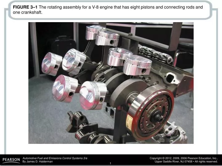
FIGURE 3–1 The rotating assembly for a V-8 engine that has eight pistons and connecting rods and one crankshaft. FIGURE 3–2 A cylinder head with four valves per cylinder, two intake valves (larger) and two exhaust valves (smaller).

E N D
FIGURE 3–1 The rotating assembly for a V-8 engine that has eight pistons and connecting rods and one crankshaft.
FIGURE 3–2 A cylinder head with four valves per cylinder, two intake valves (larger) and two exhaust valves (smaller).
FIGURE 3–3 The coolant temperature is controlled by the thermostat, which opens and allows coolant to flow to the radiator when the temperature reaches the rating temperature of the thermostat.
FIGURE 3–4 A typical lubrication system, showing the oil pan, oil pump, oil filter, and oil passages.
FIGURE 3–5 The downward movement of the piston draws the air-fuel mixture into the cylinder through the intake valve on the intake stroke. On the compression stroke, the mixture is compressed by the upward movement of the piston with both valves closed. Ignition occurs at the beginning of the power stroke, and combustion drives the piston downward to produce power. On the exhaust stroke, the upward-moving piston forces the burned gases out the open exhaust valve.
FIGURE 3–6 Cutaway of an engine showing the cylinder, piston, connecting rod, and crankshaft.
FIGURE 3–8 A horizontally opposed engine design helps to lower the vehicle’s center of gravity.
FIGURE 3–9 A longitudinally mounted engine drives the rear wheels through a transmission, driveshaft, and differential assembly.
FIGURE 3–10 Two types of front-engine, front-wheel drive mountings.
FIGURE 3–11 Cutaway of an overhead valve (OHV) V-8 engine showing the lifters, pushrods, roller rocker arms, and valves.
FIGURE 3–12 SOHC engines usually require additional components, such as a rocker arm, to operate all of the valves. DOHC engines often operate the valves directly.
FIGURE 3–13 A DOHC engine uses a camshaft for the intake valves and a separate camshaft for the exhaust valves in each cylinder head.
FIGURE 3–14 A rotary engine operates on the four-stroke cycle but uses a rotor instead of a piston and crankshaft to achieve intake, compression, power, and exhaust stroke.
FIGURE 3–15 Inline 4-cylinder engine showing principal and nonprincipal ends. Normal direction of rotation is clockwise (CW) as viewed from the front or accessory belt (nonprincipal) end.
FIGURE 3–16 The bore and stroke of pistons are used to calculate an engine’s displacement.
FIGURE 3–17 The distance between the centerline of the main bearing journal and the centerline of the connecting rod journal determines the stroke of the engine. This photo is a little unusual because it shows a V-6 with a splayed crankshaft used to even out the impulses on a 90-degree, V-6 engine design.
FIGURE 3–18 Compression ratio is the ratio of the total cylinder volume (when the piston is at the bottom of its stroke) to the clearance volume (when the piston is at the top of its stroke).
FIGURE 3–19 Combustion chamber volume is the volume above the piston with the piston is at top dead center.
FIGURE 3–20 Torque is a twisting force equal to the distance from the pivot point times the force applied expressed in units called pound-feet (lb-ft) or newton-meters (N-m).