Download
1 / 23
240 likes | 376 Vues
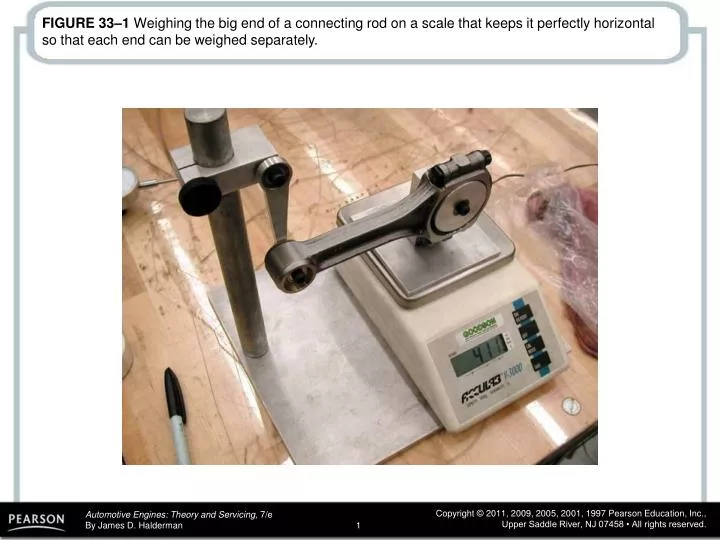
FIGURE 33–1 Weighing the big end of a connecting rod on a scale that keeps it perfectly horizontal so that each end can be weighed separately.

E N D
FIGURE 33–1 Weighing the big end of a connecting rod on a scale that keeps it perfectly horizontal so that each end can be weighed separately.
FIGURE 33–2 Removing material from the balancing pad on the small end of the rod to match it to the weight of the small end of the lightest rod being used in the engine.
FIGURE 33–3 A crankshaft with bob weights attached as well as the flex-plate and the harmonic balancer.
FIGURE 33–4 The display of a crankshaft balancer showing where weight needs to be removed to achieve a balanced assembly.
FIGURE 33–5 A drill is often used to remove weight from the crankshaft to achieve proper balance.
FIGURE 33–7 Setup needed to measure the combustion chamber volume in cubic centimeters (cc).
FIGURE 33–8 Cylinder head setup for flow testing. Note the weak valve springs that are strong enough to keep the valves shut, yet weak enough to permit the flow bench operator to vary the intake valve opening amount.
FIGURE 33–9 Modeling clay is installed around the port to duplicate the flow improvement characteristics of an intake manifold.
FIGURE 33–10 A flow bench that can measure and record the airflow through the intake and exhaust ports of each cylinder.
FIGURE 33–11 A piston stop is used to help determine top dead center.
FIGURE 33–12 The degree wheel indicates where the piston stopped near top dead center. By splitting the difference between the two readings, the true TDC (28 degrees) can be located on the degree wheel.
FIGURE 33–13 Note the setup required to degree a camshaft. The pointer, the degree wheel, and the piston stop are used to find exact top dead center.
FIGURE 33–14 Typical valve timing diagram showing the intake lobe centerline at 106 degrees ATDC.
FIGURE 33–15 A side view of a small block Chevrolet engine showing that the rocker arm is contacting the top of the valve stem. A roller-tipped rocker arm will show a more definite line of contact than a stamped steel rocker.
FIGURE 33–16 Checking where on the valve stem the marker has been worn off by the rocker arm, is the method to use to check for proper pushrod length.
FIGURE 33–17 An adjustable pushrod is adjustable for length compared to a conventional stock pushrod.