Download
1 / 67
1.24k likes | 5.42k Vues
CHAPTER 31 CRANKSHAFTS, BALANCE SHAFTS, AND BEARINGS. OBJECTIVES. After studying Chapter 31, the reader should be able to: Prepare for ASE Engine Repair (A1) certification test content area “C” (Engine Block Diagnosis and Repair). Describe the purpose and function of a crankshaft.

E N D
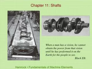
CHAPTER 31 CRANKSHAFTS, BALANCE SHAFTS, AND BEARINGS
OBJECTIVES After studying Chapter 31, the reader should be able to: • Prepare for ASE Engine Repair (A1) certification test content area “C” (Engine Block Diagnosis and Repair). • Describe the purpose and function of a crankshaft. • Discuss how to measure crankshafts. • Explain how crankshafts are machined and polished. • Discuss the purpose and function of balance shafts. • Discuss engine bearing construction and installation procedures.
Aluminum Amplitude Babbitt Bank Bearing crown Bearing shell Billet Case hardening Conformability Copper-lead alloy Corrosion resistance Counterweights Crankpins Crankshaft centerline Crush Elastomer Electroplating Embedability Fatigue life Flying web Frequency Full round bearing Fully counterweighted Half-shell bearing Hub Inertia ring Nitriding Overlay Plain bearing Precision insert-type bearing shells Primary vibration Resonate Score resistance Secondary vibration Sleeve bearing Splay angle Split-type (half-shell) bearing Spread Spun bearing Surface finish Thrust bearing Tuftriding Work hardened KEY TERMS
CRANKSHAFT • PURPOSE AND FUNCTION • MAIN BEARING JOURNALS • ROD BEARING JOURNALS • SURFACE FINISH • JOURNAL HARDNESS • Case hardening • Nitriding
FIGURE 31–1 Typical crankshaft with main journals that are supported by main bearings in the block. Rod journals are offset from the crankshaft centerline. CRANKSHAFT
FIGURE 31–2 The crankshaft rotates on main bearings. Longitudinal (end-to-end) movement is controlled by the thrust bearing. CRANKSHAFT
FIGURE 31–3 A ground surface on one of the crankshaft cheeks next to a main bearing supports thrust loads on the crank. CRANKSHAFT
FIGURE 31–4 The distance from the crankpin centerline to the centerline of the crankshaft determines the stroke, which is the leverage available to turn the crankshaft. CRANKSHAFT
FIGURE 31–5 Wide separation lines of a forged crankshaft. CRANKSHAFT CONSTRUCTION • FORGED • CAST CRANKSHAFTS • BILLET CRANKSHAFTS
FIGURE 31–6 Cast crankshaft showing the bearing journal overlap and a straight, narrow cast mold parting line. The amount of overlap determines the strength of the crankshaft. CRANKSHAFT CONSTRUCTION
FIGURE 31–7 A billet crankshaft showing how it is machined from a solid chuck of steel, usually 4340 steel, at the right and the finished crankshaft on the left. CRANKSHAFT CONSTRUCTION
FIGURE 31–8 Crankshaft sawed in half, showing drilled oil passages between the main and rod bearing journals. CRANKSHAFT OILING HOLES • The crankshaft is drilled to allow oil from the main bearing oil groove to be directed to the connecting rod bearings.
FIGURE 31–9 Typical chamfered hole in a crankshaft bearing journal. CRANKSHAFT OILING HOLES
ENGINE CRANKSHAFT TYPES • V-8 ENGINE ARRANGEMENT • FOUR-CYLINDER ENGINE CRANKSHAFTS • FIVE-CYLINDER ENGINE CRANKSHAFTS • THREE-CYLINDER ENGINE CRANKSHAFTS • INLINE SIX-CYLINDER ENGINE CRANKSHAFT • 90-DEGREE V-6 ENGINE CRANKSHAFTS • 60-DEGREE V-6 ENGINE CRANKSHAFTS
What Does a “Cross-Drilled Crankshaft” Mean? • A cross-drilled crankshaft means that there are two instead of only one oil hole leading from the main bearing journal to the rod bearing journal. Oil is supplied to the main bearing journals through oil galleries in the block. A cross-drilled crankshaft has two outlet holes for oil to reach the drilled passage that supplies oil to the rod journal.
FIGURE 31–10 A cross-drilled crankshaft is used on some production engines and is a common racing modification. What Does a “Cross-Drilled Crankshaft” Mean?
The Mysterious Engine Vibration • A Buick 3.8 liter V-6 engine vibrated the whole car after a new short block had been installed. The technician who had installed the replacement engine did all of the following: • 1. Checked the spark plugs • 2. Checked the spark plug wires • 3. Disconnected the torque converter from the flex plate (drive plate) to eliminate the possibility of a torque converter or automatic transmission pump problem • 4. Removed all accessory drive belts one at a time • Yet the vibration still existed. • Another technician checked the engine mounts and found that the left (driver’s side) engine mount was out of location, ripped, and cocked. The transmission mount was also defective. After the technician replaced both mounts and made certain that all mounts were properly set, the vibration was eliminated. The design and location of the engine mounts are critical to the elimination of vibration, especially on 90-degree V-6 engines.
FIGURE 31–11 A splayed crankshaft design is used to create an even-firing 90-degree V-6. ENGINE CRANKSHAFT TYPES
FIGURE 31–12 A fully counterweighted 4-cylinder crankshaft. COUNTERWEIGHTS • Crankshafts are balanced by counterweights, which are cast, forged, or machined as part of the crankshaft. • A crankshaft that has counterweights on both sides of each connecting rod journal is called fully counterweighted.
What Is an Offset Crankshaft? • To reduce side loads, some vehicle manufacturers offset the crankshaft from center. For example, if an engine rotates clockwise as viewed from the front, the crankshaft may be offset to the left to reduce the angle of the connecting rod during the power stroke. • The offset usually varies from 1/16 to 1/2 in., depending on make and model. Many inline 4-cylinder engines used in hybrid electric vehicles use an offset crankshaft.
FIGURE 31–13 The crank throw is halfway down on the power stroke. The piston on the left without an offset crankshaft has a sharper angle than the engine on the right with an offset crankshaft. What Is an Offset Crankshaft?
FIGURE 31–14 A crankshaft broken as a result of using the wrong torsional vibration damper. COUNTERWEIGHTS
FIGURE 31–15 The hub of the harmonic balancer is attached to the front of the crankshaft. The elastomer (rubber) between the inertia ring and the center hub allows the absorption of crankshaft firing impulses. COUNTERWEIGHTS
High Engine Speeds Require High-Performance Parts • Do not go racing with stock parts. A stock harmonic balancer can come apart and the resulting vibration can break the crankshaft if the engine is used for racing. Check the Internet or race part suppliers for the recommended balancer to use.
FIGURE 31–16 A General Motors high-performance balancer used on a race engine. High Engine Speeds Require High-Performance Parts
EXTERNALLY AND INTERNALLY BALANCED ENGINES • Most crankshaft balancing is done during manufacture. • Holes are drilled in the counterweight to lighten and improve balance. • Sometimes these holes are drilled after the crankshaft is installed in the engine. • Some manufacturers are able to control casting quality so closely that counterweight machining for balancing is not necessary. • Engine manufacturers balance an engine in one of two ways. • Externally balanced. • Internally balanced.
FIGURE 31–17 In a 4-cylinder engine, the two outside pistons move upward at the same time as the inner pistons move downward, which reduces primary unbalance. ENGINE BALANCE • PRIMARY AND SECONDARY BALANCE
FIGURE 31–18 Primary and secondary vibrations in relation to piston position. ENGINE BALANCE
FIGURE 31–19 Two counter-rotating balance shafts used to counterbalance the vibrations of a 4-cylinder engine. BALANCE SHAFTS • PURPOSE AND FUNCTION • BALANCE SHAFT APPLICATIONS
FIGURE 31–20 This General Motors 4-cylinder engine uses two balance shafts driven by a chain at the rear of the crankshaft. BALANCE SHAFTS
FIGURE 31–21 Many 90-degree V-6 engines use a balance shaft to reduce vibrations and effectively cancel a rocking motion (rocking couple) that causes the engine to rock front to back. BALANCE SHAFTS
CRANKSHAFT SERVICE • Crankshaft damage includes: • Worn journals • Scored bearing journals • Bends or warpage • Cracks • Thread damage (flywheel flange or front snout) • Worn front or rear seal surfaces
FIGURE 31–22 Scored connecting rod bearing journal. CRANKSHAFT SERVICE
CRANKSHAFT SERVICE • MEASURING THE CRANKSHAFT • CRANKSHAFT GRINDING • CRANKSHAFT POLISHING • WELDING A CRANKSHAFT • STRESS RELIEVING THE CRANKSHAFT • STORING CRANKSHAFTS
FIGURE 31–23 All crankshaft journals should be measured for diameter as well as taper and out-of-round. CRANKSHAFT SERVICE
FIGURE 31–24 Check each journal for taper and out-of-round. CRANKSHAFT SERVICE
FIGURE 31–25 The rounded fillet area of the crankshaft is formed by the corners of the grinding stone. CRANKSHAFT SERVICE
FIGURE 31–26 An excessively worn crankshaft can be restored to useful service by welding the journals, and then machining them back to the original size. FIGURE 31–27 All crankshafts should be polished after grinding. Both the crankshaft and the polishing cloth are being revolved. CRANKSHAFT SERVICE
FIGURE 31–28 Crankshafts should be stored vertically to prevent possible damage or warpage. This clever benchmounted tray for crankshafts not only provides a safe place to store crankshafts but is also out of the way and cannot be accidentally tipped. CRANKSHAFT SERVICE
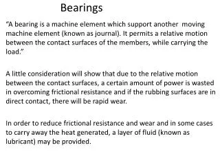
ENGINE BEARINGS • INTRODUCTION • TYPES OF BEARINGS • BEARING MATERIALS • BEARING MANUFACTURING • BEARING SIZES • BEARING LOADS • BEARING FATIGUE • BEARING CONFORMABILITY • BEARING EMBEDABILITY • BEARING DAMAGE RESISTANCE
FIGURE 31–29 The two halves of a plain bearing meet at the parting faces. ENGINE BEARINGS
FIGURE 31–30 Bearing wall thickness is not the same from the center to the parting line. This is called eccentricity and is used to help create an oil wedge between the journal and the bearing. ENGINE BEARINGS
FIGURE 31–31 Typical two- and three-layer engine bearing inserts showing the relative thickness of the various materials. ENGINE BEARINGS
FIGURE 31–32 Typical bearing shell types found in modern engines: (a) half-shell thrust bearing, (b) upper main bearing insert, (c) lower main bearing insert, (d) full round-type camshaft bearing. ENGINE BEARINGS
FIGURE 31–33 Bearings are often marked with an undersize dimension. This bearing is used on a crankshaft with a ground journal that is 0.020 in. smaller in diameter than the stock size. ENGINE BEARINGS
FIGURE 31–34 Work hardened bearing material becomes brittle and cracks, leading to bearing failure. ENGINE BEARINGS
FIGURE 31–35 Bearing material covers foreign material (such as dirt) as it embeds into the bearing. ENGINE BEARINGS
FIGURE 31–36 Bearing spread and crush. BEARING CLEARANCE • IMPORTANCE OF PROPER CLEARANCE • CHECKING BEARING CLEARANCE • BEARING SPREAD AND CRUSH
FIGURE 31–37 Bearings are thinner at the parting line faces to provide crush relief. BEARING CLEARANCE
FIGURE 31–38 Spun bearing. The lower cap bearing has rotated under the upper rod bearing. BEARING CLEARANCE