Download
1 / 49
530 likes | 862 Vues
Explore the world of crankshafts, including main bearings, balance shafts, and the significance of offset designs. Learn how proper maintenance and high-performance parts can prevent engine vibration issues.

E N D
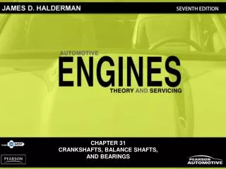
35 CRANKSHAFTS, BALANCE SHAFTS, AND BEARINGS
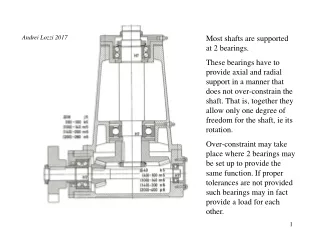
Figure 35-1 Typical crankshaft with main journals that are supported by main bearings in the block. Rod journals are offset from the crankshaft centerline.
Figure 35-2 The crankshaft rotates on main bearings. Longitudinal (end-to-end) movement is controlled by the thrust bearing.
Figure 35-3 A ground surface on one of the crankshaft cheeks next to a main bearing supports thrust loads on the crank.
Figure 35-4 The distance from the crankpin centerline to the centerline of the crankshaft determines the stroke, which is the leverage available to turn the crankshaft.
Figure 35-6 Cast crankshaft showing the bearing journal overlap and a straight, narrow cast mold parting line. The amount of overlap determines the strength of the crankshaft.
Figure 35-7 A billet crankshaft showing how it is machined from a large round roll of steel, usually 4340 steel, at the right and the finished crankshaft on the left.
Figure 35-8 Crankshaft sawed in half, showing drilled oil passages between the main and rod bearing journals.
Figure 35-9 Typical chamfered hole in a crankshaft bearing journal.
FREQUENTLY ASKED QUESTION: What Does a “Cross-Drilled Crankshaft” Mean? A cross-drilled crankshaft means that there are two instead of only one oil hole leading from the main bearing journal to the rod bearing journal. Oil is supplied to the main bearing journals through oil galleries in the block. A cross-drilled crankshaft has two outlet holes for oil to reach the drilled passage that supplies oil to the rod journal. - SEE FIGURE 35–10 .
Figure 35-10 A cross-drilled crankshaft is used on some production engines and is a common racing modification.
REAL WORLD FIX: The Mysterious Engine Vibration A Buick 3.8 liter V-6 engine vibrated the whole car after a new short block had been installed. The technician who had installed the replacement engine did all of the following: 1. Checked the spark plugs 2. Checked the spark plug wires 3. Disconnected the torque converter from the flex plate (drive plate) to eliminate the possibility of a torque converter or automatic transmission pump problem 4. Removed all accessory drive belts one at a time Yet the vibration still existed. Another technician checked the engine mounts and found that the left (driver’s side) engine mount was out of location, ripped, and cocked. The transmission mount was also defective. After the technician replaced both mounts and made certain that all mounts were properly set, the vibration was eliminated. The design and location of the engine mounts are critical to the elimination of vibration, especially on 90-degree V-6 engines.
Figure 35-11 A splayed crankshaft design is used to create an even-firing 90-degree V-6.
Figure 35-12 A fully counterweighted 4-cylinder crankshaft.
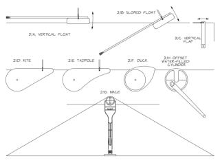
FREQUENTLY ASKED QUESTION: What Is an Offset Crankshaft? To reduce side loads, some vehicle manufacturers offset the crankshaft from center. For example, if an engine rotates clockwise as viewed from the front, the crankshaft may be offset to the left to reduce the angle of the connecting rod during the power stroke. - SEE FIGURE 35–13 . The offset usually varies from 1/16 to 1/2 in., depending on make and model. Many inline 4-cylinder engines used in hybrid electric vehicles use an offset crankshaft.
Figure 35-13 The crank throw is halfway down on the power stroke. The piston on the left without an offset crankshaft has a sharper angle than the engine on the right with an offset crankshaft.
Figure 35-14 A crankshaft broken as a result of using the wrong torsional vibration damper.
Figure 35-15 The hub of the harmonic balancer is attached to the front of the crankshaft. The elastomer (rubber) between the inertia ring and the center hub allows the absorption of crankshaft firing impulses.
TECH TIP: High Engine Speeds Require High-Performance Parts Do not go racing with stock parts. A stock harmonic balancer can come apart and the resulting vibration can break the crankshaft if the engine is used for racing. Check the Internet or race part suppliers for the recommended balancer to use. - SEE FIGURE 35–16 .
Figure 35-16 A General Motors high-performance balancer used on a race engine.
Figure 35-17 In a 4-cylinder engine, the two outside pistons move upward at the same time as the inner pistons move downward, which reduces primary unbalance.
Figure 35-18 Primary and secondary vibrations in relation to piston position.
Figure 35-19 Two counterrotating balance shafts used to counterbalance the vibrations of a 4-cylinder engine
Figure 35-20 This General Motors 4-cylinder engine uses two balance shafts driven by a chain at the rear of the crankshaft.
Figure 35-21 Many 90-degree V-6 engines use a balance shaft to reduce vibrations and effectively cancel a rocking motion (rocking couple) that causes the engine to rock front to back.
Figure 35-23 All crankshaft journals should be measured for diameter as well as taper and out-of-round.
Figure 35-24 Check each journal for taper and out-of-round.
Figure 35-25 The rounded fillet area of the crankshaft is formed by the corners of the grinding stone.
Figure 35-26 An excessively worn crankshaft can be restored to useful service by welding the journals, and then machining them back to the original size.
Figure 35-27 All crankshafts should be polished after grinding. Both the crankshaft and the polishing cloth are being revolved.
Figure 35-28 Crankshafts should be stored vertically to prevent possible damage or warpage. This clever bench-mounted tray for crankshafts not only provides a safe place to store crankshafts but is also out of the way and cannot be accidentally tipped.
Figure 35-29 The two halves of a plain bearing meet at the parting faces.
Figure 35-30 Bearing wall thickness is not the same from the center to the parting line. This is called eccentricity and is used to help create an oil wedge between the journal and the bearing.
Figure 35-31 Typical two- and three-layer engine bearing inserts showing the relative thickness of the various materials.
Figure 35-32 Typical bearing shell types found in modern engines: (a) half-shell thrust bearing, (b) upper main bearing insert, (c) lower main bearing insert, (d) full round-type camshaft bearing.
Figure 35-33 Bearings are often marked with an undersize dimension. This bearing is used on a crankshaft with a ground journal that is 0.020 in. smaller in diameter than the stock size.
Figure 35-34 Work hardened bearing material becomes brittle and cracks, leading to bearing failure.
Figure 35-35 Bearing material covers foreign material (such as dirt) as it embeds into the bearing.
Figure 35-37 Bearings are thinner at the parting line faces to provide crush relief.
Figure 35-38 Spun bearing. The lower cap bearing has rotated under the upper rod bearing.
Figure 35-39 The tang and slot help index the bearing in the bore.
Figure 35-40 Many bearings are manufactured with a groove down the middle to improve the oil flow around the main journal.
TECH TIP: Count Your Blessings and Your Pan Bolts! Replacing cam bearings can be relatively straightforward or can involve keeping count of the number of oil pan bolts. For example, Buick-built V-6 engines use different cam bearings depending on the number of bolts used to hold the oil pan to the block. • Fourteen bolts in the oil pan. The front bearing is special, but the rest of the bearings are the same. • Twenty bolts in the oil pan. Bearings 1 and 4 use two oil feed holes. Bearings 2 and 3 use single oil feed holes.
Figure 35-41 Cam-in-block engines support the camshaft with sleeve-type bearings.
Figure 35-42 Camshaft bearings must be installed correctly so that oil passages are not blocked.
Figure 35-43 Some overhead camshaft engines use split bearing inserts.