Download
1 / 178
1.78k likes | 1.82k Vues
Understand the role of VLANs in switching networks, trunk port configuration, DTP setup, and troubleshooting in VLAN-segmented environments. Learn IP communication principles and subnetting concepts for optimized network performance.

E N D
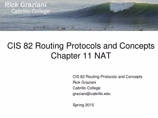
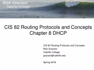
CIS 82 Routing and Switching EssentialsChapter 6 VLANs CIS 82 Routing Protocols and Concepts Rick Graziani Cabrillo College graziani@cabrillo.edu Spring 2018
Chapter 6: Objectives • Explain the purpose of VLANs in a switched network. • Analyze how a switch forwards frames based on VLAN configuration in a multi-switched environment. • Configure a switch port to be assigned to a VLAN based on requirements. • Configure a trunk port on a LAN switch. • Configure Dynamic Trunk Protocol (DTP). • Troubleshoot VLAN and trunk configurations in a switched network. • Configure security features to mitigate attacks in a VLAN-segmented environment. • Explain security best practices for a VLAN-segmented environment.
It’s all about the IP Address Emmalia, you are in my neighborhood so I can take the letter to you! Rick Santa Cruz, Ca Emmalia Santa Cruz, Ca Lucia, I see by your address that you are somewhere else. So I have to take your letter to the Post Office. • Even if two houses are on the same street, you only know the address so must take it to the local post office Rick Santa Cruz, Ca Lucia Capitola, Ca Emmalia Santa Cruz, Ca
Understanding IP communications 192.168.10.0/24 Subnet MAC aa.aa MAC bb.bb 192.168.10.0/24 Subnet A B 192.168.10.10 255.255.255.0 192.168.10.11 255.255.255.0 Destination Address bb.bb Source Address aa.aa Type IP DA 192.168.10.11 FCS • Devices can only communicate with other devices on the same subnet • A knows that it is on the 192.168.10.0/24 subnet (AND operation with its IP address and subnet mask). (Same subnet = Same subnet mask) • A knows that B (192.168.1.11) is on its same subnet (AND operation with B’s IP address and A’s subnet mask) SAME Subnet A can reach B directly without going through a router B 192.168.10.11 AND 255.255.255.0 -------------------- 192.168.10.0 A 192.168.10.10 AND 255.255.255.0 -------------------- 192.168.10.0
Understanding IP communications 192.168.10.0/24 Subnet MAC aa.aa MAC cc.cc 192.168.20.0/24 Subnet A C 192.168.10.10 255.255.255.0 192.168.20.12 255.255.255.0 Destination Address Source Address Type IP DA 192.168.20.12 FCS • Devices can only communicate with other devices on the same subnet • A knows that it is on the 192.168.10.0/24 subnet (AND operation with its IP address and subnet mask) (Same subnet = Same subnet mask) • A knows that C (192.168.20.12) is on a differentsubnet (AND operation with B’s IP address and A’s subnet mask) – Can’t get there directly! DIFFERENT Subnets A can NOT reach B directly. Must go through a router B 192.168.20.12 AND 255.255.255.0 -------------------- 192.168.20.0 A 192.168.10.10 AND 255.255.255.0 -------------------- 192.168.10.0
192.168.20.0/24 Subnet 192.168.10.0/24 Subnet MAC aa.aa MAC 11.11 MAC 22.22 A C MAC cc.cc 192.168.10.1 255.255.255.0 192.168.20.1 255.255.255.0 192.168.10.10 255.255.255.0 192.168.20.12 255.255.255.0 Destination Address 11.11 Source Address aa.aa Type IP DA 192.168.20.12 FCS Destination Address cc.cc Source Address 22.22 Type IP DA 192.168.20.12 FCS • A sends packet to devices in a DIFFERENT subnet directly to a router which is on the same subnet as A. • The router will take care of it from there. DIFFERENT Subnets A can NOT reach B directly. Must go through a router 192.168.20.11 AND 255.255.255.0 -------------------- 192.168.20.0 192.168.10.10 AND 255.255.255.0 -------------------- 192.168.10.0
Understanding IP communications A B 192.168.10.10 255.255.255.0 192.168.10.11 255.255.255.0 A C 192.168.10.10 255.255.255.0 192.168.20.12 255.255.255.0 • Devices can only communicate with other devices on the same subnet • Otherwise, they must go through a router, that is on its same subnet A C 192.168.10.1 255.255.255.0 192.168.20.1 255.255.255.0 192.168.10.10 255.255.255.0 192.168.20.12 255.255.255.0
Definition: VLAN “A VLAN is a virtual LAN that logically segments switched networks based on functions, projectteams, or applications of the organization regardless of the physical location or connections to the network.”
TO CLEAR A SWITCH • ALWAYS DO THE FOLLOWING TO CLEAR A SWITCH!! S1# delete vlan.dat Delete filename [vlan.dat]? Delete flash:/vlan.dat? [confirm] S1# erase startup-config Erasing the nvramfilesystem will remove all configuration files! Continue? [confirm] [OK] Erase of nvram: complete %SYS-7-NV_BLOCK_INIT: Initialized the geometry of nvram S1# reload Proceed with reload? [confirm]
Default VLAN Assignment Default: All ports in the same VLAN (subnet) Switch# show vlan VLAN Name Status Ports ---- -------------------------------- --------- ------------------------------- 1 default active Fa0/1, Fa0/2, Fa0/3, Fa0/4 Fa0/5, Fa0/6, Fa0/7, Fa0/8 Fa0/9, Fa0/10, Fa0/11, Fa0/12 Fa0/13, Fa0/14, Fa0/15, Fa0/16 Fa0/17, Fa0/18, Fa0/19, Fa0/20 Fa0/21, Fa0/22, Fa0/23, Fa0/24 Gig0/1, Gig0/2 <output omitted>
Default VLAN Assignment Default: All ports in the same VLAN ARP Request Broadcast A B C D • Hosts can communicate with each other because: • Same IP subnet • Switch ports are on the same VLAN (subnet) • Can A, B, C and D ping each other? • If A did an ARP request for B, who would see this Ethernet broadcast? 192.168.10.10 255.255.255.0 192.168.10.11 255.255.255.0 192.168.10.12 255.255.255.0 192.168.10.13 255.255.255.0
VLAN Definitions • A VLAN is a logical partition of a Layer 2 network. • Multiple partitions can be created, allowing for multiple VLANs to co-exist. • Each VLAN is a broadcast domain, usually with its own IP network. • VLANs are mutually isolated and packets can only pass between them via a router. • The partitioning of the Layer 2 network takes place inside a Layer 2 device, usually via a switch. • The hosts grouped within a VLAN are unaware of the VLAN’s existence.
With a single VLANs (“no VLANs”) MAC aa.aa MAC bb.bb MAC cc.cc A B C MAC dd.dd D • You can do this but devices can only communicate with each other that are on the same IP subnet…. Unless you have a ….. • ROUTER (coming) • Who can A Ping? B ping? C ping? D ping? 192.168.10.10 255.255.255.0 192.168.10.11 255.255.255.0 192.168.20.12 255.255.255.0 192.168.20.13 255.255.255.0
A single VLAN (“no VLANs”) means no segmentation ARP Request Broadcast Wasted bandwidth MAC aa.aa MAC bb.bb MAC cc.cc A B C MAC dd.dd D • Who can A Ping? B ping? C ping? D ping? • If A did an ARP request for B, who would see this Ethernet broadcast? • If C did an ARP request for D, who would see this Ethernet broadcast? • Remember: ARP requests are only when the source IP address and the destination IP address are on the SAME SUBNET. 192.168.10.10 255.255.255.0 192.168.10.11 255.255.255.0 192.168.20.12 255.255.255.0 192.168.20.13 255.255.255.0
A single VLAN (“no VLANs”) means no segmentation ARP Request Broadcast A B C D • Who can A Ping? B ping? C ping? D ping? • If A did an ARP request for B, who would see this Ethernet broadcast? • If C did an ARP request for D, who would see this Ethernet broadcast? • Remember: ARP requests are only when the source IP address and the destination IP address are on the SAME SUBNET. 192.168.10.10 255.255.255.0 192.168.10.11 255.255.255.0 192.168.20.12 255.255.255.0 192.168.20.13 255.255.255.0
VLANs and IP Addresses/Masks • VLANs are configured on the switch port • IP Addresses and subnet masks are configured on the devices that connect to the switch ports. • VLAN on the switch must match the IP network address of the device.
Configured for VLAN 10 Configured for VLAN 10 Configured for VLAN 20 Configured for VLAN 20 MAC aa.aa MAC bb.bb MAC cc.cc A B C MAC dd.dd D • VLANs are configured on the switch port • IP Addresses and subnet masks are configured on the devices that connect to the switch ports. • VLAN on the switch must match the IP network address of the device. 192.168.10.10 255.255.255.0 192.168.10.11 255.255.255.0 192.168.20.12 255.255.255.0 192.168.20.13 255.255.255.0
BEFORE (DEFAULT CONFIGURATION) A B C D 192.168.10.10 255.255.255.0 192.168.10.11 255.255.255.0 192.168.10.12 255.255.255.0 192.168.10.13 255.255.255.0 Default: All ports in the same VLAN (subnet) Switch# show vlan VLAN Name Status Ports ---- -------------------------------- --------- ------------------------------- 1 default active Fa0/1, Fa0/2, Fa0/3, Fa0/4 Fa0/5, Fa0/6, Fa0/7, Fa0/8 Fa0/9, Fa0/10, Fa0/11, Fa0/12 Fa0/13, Fa0/14, Fa0/15, Fa0/16 Fa0/17, Fa0/18, Fa0/19, Fa0/20 Fa0/21, Fa0/22, Fa0/23, Fa0/24 Gig0/1, Gig0/2
AFTER CONFIGURATION A B C D 192.168.10.10 255.255.255.0 192.168.10.11 255.255.255.0 192.168.20.12 255.255.255.0 192.168.20.13 255.255.255.0 Switch# show vlan VLAN Name Status Ports ---- -------------------------------- --------- ------------------------------- 10 active Fa0/1, Fa0/2, Fa0/3, Fa0/4 Fa0/5, Fa0/6, Fa0/7, Fa0/8 Fa0/9, Fa0/10, Fa0/11, Fa0/12, Gig0/1 20activeFa0/13, Fa0/14, Fa0/15, Fa0/16 Fa0/17, Fa0/18, Fa0/19, Fa0/20 Fa0/21, Fa0/22, Fa0/23, Fa0/24, Gig0/2
VLANs give proper segmentation – Like having separate switches VLANs do not have to be configured contiguously on the switch. ARP Request Broadcast ARP Request Broadcast A B C D • VLANs segment switches in to different VLANs or Subnets • Think of it like having separate switches • Who can A Ping? B ping? C ping? D ping? • If A did an ARP request for B, who would see this Ethernet broadcast? • If C did an ARP request for D, who would see this Ethernet broadcast? 192.168.10.10 255.255.255.0 192.168.10.11 255.255.255.0 192.168.20.12 255.255.255.0 192.168.20.13 255.255.255.0
Router and subnets/VLANs • Router is required to connect (route) between subnets/VLANs MAC aa.aa MAC bb.bb MAC cc.cc A B C MAC dd.dd D 192.168.10.10 255.255.255.0 192.168.10.11 255.255.255.0 192.168.20.12 255.255.255.0 192.168.20.13 255.255.255.0
MAC 22.22 192.168.20.1 255.255.255.0 PCA> ping 192.168.20.12 MAC 11.11 192.168.10.1 255.255.255.0 • Router is required to connect (route) between subnets/VLANs • In this example, a single router with two IP addresses, one on each subnet, is connected to the switch. • Each of the router’s interfaces is connected to a proper VLAN port on the switch to match it’s IP subnet. (Just like the host computers!) MAC aa.aa MAC bb.bb MAC cc.cc A B C MAC dd.dd D 192.168.10.10 255.255.255.0 192.168.10.11 255.255.255.0 192.168.20.12 255.255.255.0 192.168.20.13 255.255.255.0
MAC 22.22 192.168.20.1 255.255.255.0 PCA> ping 192.168.20.12 MAC 11.11 192.168.10.1 255.255.255.0 • A does an ARP Request for 192.168.10.1 (Default gateway). • Gets ARP Reply • A adds MAC and IP to ARP Cache MAC aa.aa MAC bb.bb MAC cc.cc A B C MAC dd.dd D 192.168.10.10 255.255.255.0 192.168.10.11 255.255.255.0 192.168.20.12 255.255.255.0 192.168.20.13 255.255.255.0 ARP Cache 192.168.10.1 <-> 11.11
MAC 22.22 192.168.20.1 255.255.255.0 PCA> ping 192.168.20.12 MAC 11.11 192.168.10.1 255.255.255.0 • A sends Ethernet frame to default gateway, the router MAC aa.aa MAC bb.bb MAC cc.cc A B C MAC dd.dd D 192.168.10.10 255.255.255.0 192.168.10.11 255.255.255.0 192.168.20.12 255.255.255.0 192.168.20.13 255.255.255.0 Destination Address 11.11 Source Address aa.aa Type IP (ICMP) DA 192.168.20.12 FCS
ARP Cache 192.168.20.12 <-> cc.cc MAC 22.22 192.168.20.1 255.255.255.0 MAC 11.11 192.168.10.1 255.255.255.0 • Router does an ARP Request for 192.168.20.12 (Destination IP). • Gets ARP Reply • Router adds MAC and IP to ARP Cache MAC aa.aa MAC bb.bb MAC cc.cc A B C MAC dd.dd D 192.168.10.10 255.255.255.0 192.168.10.11 255.255.255.0 192.168.20.12 255.255.255.0 192.168.20.13 255.255.255.0 PCA> ping 192.168.20.12
MAC 22.22 192.168.20.1 255.255.255.0 PCA> ping 192.168.20.12 MAC 11.11 192.168.10.1 255.255.255.0 • Router sends Ethernet frame to final destination, PC-C MAC aa.aa MAC bb.bb MAC cc.cc A B C MAC dd.dd D 192.168.10.10 255.255.255.0 192.168.10.11 255.255.255.0 192.168.20.12 255.255.255.0 192.168.20.13 255.255.255.0 Destination Address cc.cc Source Address 22.22 Type IP (ICMP) DA 192.168.20.12 FCS
MAC 22.22 192.168.20.1 255.255.255.0 PCA> ping 192.168.20.12 .!!!! MAC 11.11 192.168.10.1 255.255.255.0 MAC aa.aa MAC bb.bb MAC cc.cc A B C MAC dd.dd D 192.168.10.10 255.255.255.0 192.168.10.11 255.255.255.0 192.168.20.12 255.255.255.0 192.168.20.13 255.255.255.0 Destination Address 22.22 Source Address cc.cc Type IP (ICMP) DA 192.168.10.10 FCS Destination Address aa.aa Source Address 11.11 Type IP (ICMP) DA 192.168.10.10 FCS
Benefits of VLANs • Security: • Improved by isolating user access to sensitive data and applications. • Cost reduction: • Reduces the need for expensive network upgrades and more efficient use of existing bandwidth and uplinks. • Smaller Broadcast Domains: • Divide a network into smaller logical networks, resulting in lower susceptibility to broadcast storms. • Better performance: • Divides the flat Layer 2 networks into multiple broadcast domains reducing unnecessary traffic on the network and boosts performance. • Improved IT staff efficiency: • Makes the network easier to manage.
How many VLANs can you configure on a switch? It depends…. on the switch and the switch’s capabilities and what you require.
Default VLAN Assignment Switch# show vlan VLAN Name Status Ports ---- -------------------------------- --------- ------------------------------- 1 default active Fa0/1, Fa0/2, Fa0/3, Fa0/4 Fa0/5, Fa0/6, Fa0/7, Fa0/8 Fa0/9, Fa0/10, Fa0/11, Fa0/12 Fa0/13, Fa0/14, Fa0/15, Fa0/16 Fa0/17, Fa0/18, Fa0/19, Fa0/20 Fa0/21, Fa0/22, Fa0/23, Fa0/24 Gig0/1, Gig0/2 1002 fddi-default act/unsup 1003 token-ring-default act/unsup 1004 fddinet-default act/unsup 1005 trnet-default act/unsup VLAN Type SAID MTU Parent RingNo BridgeNo Stp BrdgMode Trans1 Trans2 ---- ----- ---------- ----- ------ ------ -------- ---- -------- ------ ------ 1 enet 100001 1500 - - - - - 0 0 1002 fddi 101002 1500 - - - - - 0 0 1003 tr 101003 1500 - - - - - 0 0 1004 fdnet 101004 1500 - - - ieee - 0 0 1005 trnet 101005 1500 - - - ibm - 0 0 Switch#
Normal Range VLANs Switch# show vlan VLAN Name Status Ports ---- -------------------------------- --------- ------------------------------- 1 default active Fa0/1, Fa0/2, Fa0/3, Fa0/4 Fa0/5, Fa0/6, Fa0/7, Fa0/8 Fa0/9, Fa0/10, Fa0/11, Fa0/12 Fa0/13, Fa0/14, Fa0/15, Fa0/16 Fa0/17, Fa0/18, Fa0/19, Fa0/20 Fa0/21, Fa0/22, Fa0/23, Fa0/24 Gig0/1, Gig0/2 1002 fddi-default act/unsup 1003 token-ring-default act/unsup 1004 fddinet-default act/unsup 1005 trnet-default act/unsup • Used in small- and medium-sized business and enterprise networks. • VLAN Range: 1 – 1005 • Reserved VLANs: VLANs 1, 1002 – 1005 • Configurations stored in vlan.dat in flash memory. • Note: • VLAN Trunking Protocol (VTP) can manage normal range VLANs.
Extended Range VLANs • Used in Service Provider networks (great number of customers) or large, global enterprises. • VLAN Range: 1006 - 4094. • Support fewer VLAN features than normal range VLANs. • Saved in the running configuration file.
It can support up to 255 normal range and extended range VLANs.
Types of VLANs • Default VLAN (VLAN 1 by default) • Native VLAN (VLAN 1 by default) • Used for untagged traffic (later) • User VLANs • Each IP subnet is a separate VLAN • Management VLAN • VLAN to connect to infrastructure devices such a switches • Voice VLAN • VLAN used to connect IP phones • Guest VLAN • For to connect guests and others who do not have access to internal resources, perhaps Internet access only • Garbage VLAN • For unused ports not yet configured for a specific VLAN
User VLAN examples VLAN = Subnet • Business VLANs • IT VLAN • HR VLAN • Sales VLAN • College • Student VLAN • Faculty VLAN • Guest VLAN
Default VLAN VLAN 1 Default VLAN Native VLAN Un-tagged (If trunking there is no 802.1Q or ISL encapsulation) CDP, VTP, PAgP, LACP, DTP, BPDUs • By default all traffic is carried across VLAN 1. • By default all ports are on VLAN 1 • VLAN 1 is: • The default VLAN (all user traffic) • Native VLAN: No trunking encapsulation even if configured as a trunk coming). • All Layer 2 control traffic (e.g., DTP, VTP, STP BPDUs, PAgP, LACP, CDP, etc.), are associated with VLAN 1
Default VLAN 1 S1# show vlan VLAN Name Status Ports ---- -------------------------------- --------- ------------------------------- 1 default active Fa0/1, Fa0/2, Fa0/3, Fa0/4 Fa0/5, Fa0/6, Fa0/7, Fa0/8 Fa0/9, Fa0/10, Fa0/11, Fa0/12 Fa0/13, Fa0/14, Fa0/15, Fa0/16 Fa0/17, Fa0/18, Fa0/19, Fa0/20 Fa0/21, Fa0/22, Fa0/23, Fa0/24 Gi0/1, Gi0/2 • VLAN 1 cannot be deleted • Security best practices: • Avoid using VLAN 1 for all VLANs other that control traffic which must be on VLAN1 • In other words, create additional VLANs
User or Data VLANs MAC aa.aa MAC bb.bb MAC cc.cc A B C MAC dd.dd D • These are VLANs used for different user VLANs/subnets • For user data traffic • What about the ports not in the Red or Blue VLAN? • They are still in VLAN 1 (default VLAN) • Change them to the Voice (VoIP) VLAN later. 192.168.10.10 255.255.255.0 192.168.10.11 255.255.255.0 192.168.20.12 255.255.255.0 192.168.20.13 255.255.255.0 HR Department Sales Department
Creating Static User VLANs S1# configure terminal S1(config)# vlan10 S1(config-vlan)# name HR S1(config-vlan)# exit S1(config)# interface fastethernet 0/2 S1(config-if)# switchport mode access S1(config-if)# switchport access vlan10 S1(config-if)# end S1# VLAN name is optional Single host attached, not another switch (trunk)… later • Ports on a switch are manually assigned (CLI) to a VLAN. • If you assign an interface to a VLAN that does not exist, the new VLAN is created for you. • Note: Dynamic VLANs can be configured using a special server called a VLAN Membership Policy Server (VMPS). Beyond the scope of this course. VLAN 10 assigned to the port
Configuring a Range of Ports S1(config)# interface range fastethernet 0/1 - 10 S1(config-if-range)# switchport mode access S1(config-if-range)# switchport access vlan10 S1(config-if-range)# exit S1(config)# interface gigabitethernet 0/1 S1(config-if)# switchport mode access S1(config-if)# switchport access vlan10 S1(config-if)# end S1#
Configuring a Range of Ports S1(config)# vlan20 S1(config-vlan)# name SALES S1(config-vlan)# exit S1(config)# interface range fastethernet 0/13 - 22 S1(config-if-range)# switchport mode access S1(config-if-range)# switchport access vlan20 S1(config-if-range)# exit S1(config)# interface gigabitethernet 0/2 S1(config-if)# switchport mode access S1(config-if)# switchport access vlan20 S1(config-if)# end S1#
Configuring a Range of Ports S1# show vlan VLAN Name Status Ports ---- -------------------------------- --------- ------------------------------- 1 default active Fa0/11, Fa0/12, Fa0/23, Fa0/24 10 HR active Fa0/1, Fa0/2, Fa0/3, Fa0/4 Fa0/5, Fa0/6, Fa0/7, Fa0/8 Fa0/9, Fa0/10, Gi0/1 20 SALES active Fa0/13, Fa0/14, Fa0/15, Fa0/16 Fa0/17, Fa0/18, Fa0/19, Fa0/20 Fa0/21, Fa0/22, Gi0/2
Verifying VLAN Port Parameters S1# show interface fa 0/1 switchport Name: Fa0/1 Switchport: Enabled Administrative Mode: static access Operational Mode: down Administrative Trunking Encapsulation: dot1q Negotiation of Trunking: Off Access Mode VLAN: 10 (HR) Trunking Native Mode VLAN: 1 (default) Administrative Native VLAN tagging: enabled Voice VLAN: none Operational private-vlan: none Trunking VLANs Enabled: ALL <some output omitted> S1#
Verifying VLAN Port Parameters S1# show interface fa 0/11 switchport Name: Fa0/11 Switchport: Enabled Administrative Mode: dynamic auto Operational Mode: down Administrative Trunking Encapsulation: dot1q Negotiation of Trunking: On Access Mode VLAN: 1 (default) Trunking Native Mode VLAN: 1 (default) Administrative Native VLAN tagging: enabled Voice VLAN: none
Verifying VLANs S1# show vlan brief VLAN Name Status Ports ---- -------------------------------- --------- ------------------------------- 1 default active Fa0/11, Fa0/12, Fa0/23, Fa0/24 10 HR active Fa0/1, Fa0/2, Fa0/3, Fa0/4 Fa0/5, Fa0/6, Fa0/7, Fa0/8 Fa0/9, Fa0/10, Gi0/1 20 SALES active Fa0/13, Fa0/14, Fa0/15, Fa0/16 Fa0/17, Fa0/18, Fa0/19, Fa0/20 Fa0/21, Fa0/22, Gi0/2 1002 fddi-default act/unsup 1003 token-ring-default act/unsup 1004 fddinet-default act/unsup 1005 trnet-default act/unsup S1#
Verifying VLANs S1# show vlan id 10 VLAN Name Status Ports ---- -------------------------------- --------- ------------------------------- 10 HR active Fa0/1, Fa0/2, Fa0/3, Fa0/4 Fa0/5, Fa0/6, Fa0/7, Fa0/8 Fa0/9, Fa0/10, Gi0/1 <output omitted> S1# show vlan name SALES VLAN Name Status Ports ---- -------------------------------- --------- ------------------------------- 20 SALES active Fa0/13, Fa0/14, Fa0/15, Fa0/16 Fa0/17, Fa0/18, Fa0/19, Fa0/20 Fa0/21, Fa0/22, Gi0/2 <output omitted> S1#
Verifying VLANs S1(config)# vlan 444 S1(config-vlan)# end S1# show vlan VLAN Name Status Ports ---- -------------------------------- --------- ------------------------------- 1 default active Fa0/11, Fa0/12, Fa0/23, Fa0/24 10 HR active Fa0/1, Fa0/2, Fa0/3, Fa0/4 Fa0/5, Fa0/6, Fa0/7, Fa0/8 Fa0/9, Fa0/10, Gi0/1 20 SALES active Fa0/13, Fa0/14, Fa0/15, Fa0/16 Fa0/17, Fa0/18, Fa0/19, Fa0/20 Fa0/21, Fa0/22, Gi0/2 444 VLAN0444 active <output omitted> S1# conf t S1(config)# no vlan 444 S1(config)# end S1# show vlan id 444 VLAN id 444 not found in current VLAN database S1#
Management VLAN 1 VLAN 1 192.168.10.254 SSH to 192.168.10.254 S1(config)# inter vlan 1 S1(config-if)# description Management VLAN S1(config-if)# ip address 192.168.10.254 255.255.255.0 S1(config-if)# no shutdown • A switch can be managed via HTTP, Telnet, SSH, or SNMP. • A management VLAN is used to manage the infrastructure devices including switches, routers, AP, etc. • Security best practice is to change the management VLAN to a VLAN other than VLAN 1. • We will discuss this later, because we will need to route to the management VLAN.
Native VLAN • A native VLAN is assigned to an IEEE 802.1Q trunk port (later). • Incoming traffic can be tagged (VLAN) or untagged traffic. • Native VLANs are set out in the IEEE 802.1Q specification to maintain backward compatibility with untagged traffic. • Security best practice is to change the native VLAN to a VLAN other than VLAN 1. • We will come back to this later…