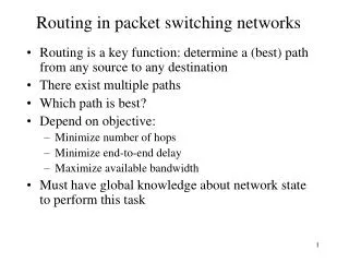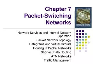
Routing & Switching
Routing & Switching. Umar Kalim Dept. of Communication Systems Engineering umar.kalim@niit.edu.pk http://www.niit.edu.pk/~umarkalim 20/03/2007. Ref: CSci5211 Univ. of Minnesota. Agenda. Virtual Circuit Switching Model Datagram Switching Model Router Tables - Overview

Routing & Switching
E N D
Presentation Transcript
Routing & Switching Umar Kalim Dept. of Communication Systems Engineering umar.kalim@niit.edu.pk http://www.niit.edu.pk/~umarkalim 20/03/2007 Ref: CSci5211 Univ. of Minnesota
Agenda • Virtual Circuit Switching Model • Datagram Switching Model • Router Tables - Overview • Longest Prefix Match • ARP • ICMP
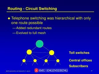
Virtual Circuit vs. Datagram • Objective of both: move packets through routers from source to destination • Datagram Model: • Routing: determine next hop to each destination a priori • Forwarding: destination address in packet header, used at each hop to look up for next hop • routes may change during “session” • analogy: driving, asking directions at every corner gas station, or based on the road signs at every turn • Virtual Circuit Model: • Routing: determine a path from source to each destination • “Call” Set-up: fixed path (“virtual circuit”) set up at “call” setup time, remains fixed thru “call” • Data Forwarding: each packet carries “tag” or “label” (virtual circuit id, VCI), which determines next hop • routers maintain”per-call” state
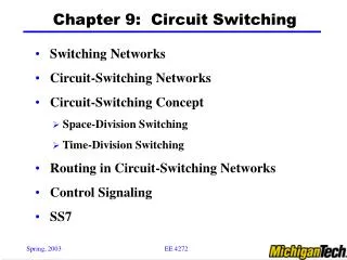
0 0 0 1 3 11 3 1 3 1 Switch 1 Switch 2 2 2 2 5 0 7 Switch 3 3 1 Host B Host A 4 Virtual Circuit Switching • Explicit connection setup (and tear-down) phase • Subsequence packets follow same circuit • Sometimes called connection-oriented model still packet switching, not circuit switching! • Analogy: phone call • Each switch maintains a VC table 2
Datagram Switching • No connection setup phase • Each packet forwarded independently • Sometimes called connectionless model • Analogy: postal system • Each switch maintains a forwarding (routing) table
Virtual Circuit Forwarding Table a.k.a. VC (Translation) Table (switch 1, port 2) Datagram Forwarding Table (switch 1) Forwarding Tables: VC vs. Datagram
call setup/teardown for each call before data can flow need special control protocol: “signaling” every router on source-dest path maintains “state” (VCI translation table) for each passing call VCI translation table at routers along the path of a call “weaving together” a “logical connection” for the call link, router resources (bandwidth, buffers) may be reserved and allocated to each VC to get “circuit-like” performance “source-to-dest path behaves much like telephone circuit” (but actually over packet network) More on Virtual Circuits
Virtual Circuit Setup/Teardown Call Set-Up: • Source: select a path from source to destination • Use routing table (which provides a “map of network”) • Source: send VC setup request control (“signaling”) packet • Specify path for the call, and also the (initial) output VCI • perhaps also resources to be reserved, if supported • Each router along the path: • Determine output port and choose a (local) output VCI for the call • need to ensure that no two distinct VCs leaving the same output port have the same VCI! • Update VCI translation table (“forwarding table”) • add an entry, establishing an mapping between incoming VCI & port no. and outgoing VCI & port no. for the call Call Tear-Down: similar, but remove entry instead
1 1 green call four “calls” going thru the router, each entry corresponding one call purple call blue call orange call VCI translation table (aka “forwarding table”), built at call set-up phase 2 3 2 2 1 1 During data packet forwarding phase, input VCI is used to look up the table, and is “swapped” w/ output VCI (VCI translation, or “label swapping”)
Virtual Circuit: Example “call” from host A to host B along path: host A router 1 router 2 router 3 host B • each router along path maintains an entry for the call in its VCI translation table • the entries piece together a “logical connection” for the call Router 4 0 Router 1 3 1 2 Router 2 2 3 1 5 11 0 Host A 7 Router 3 0 1 3 4 Host B 2
Virtual Circuit Model: Pros and Cons • Full RTT for connection setup • before sending first data packet. • Setup request carries full destination address • each data packet contains only a small identifier • If a switch or a link in a connection fails • new connection needs to be established. • Provides opportunity to reserve resources.
ATM Networks Study for Reference
no call setup at network layer routers: no state about end-to-end connections no network-level concept of “connection” packets forwarded using destination host address packets between same source-dest pair may take different paths, when intermediate routes change! application transport network data link physical application transport network data link physical 1. Send data 2. Receive data Datagram Networks: the Internet model
Datagram Model • There is no round trip delay waiting for connection setup; a host can send data as soon as it is ready. • Source host has no way of knowing if the network is capable of delivering a packet or if the destination host is even up. • Since packets are treated independently, it is possible to route around link and node failures. • Since every packet must carry the full address of the destination, the overhead per packet is higher than for the connection-oriented model.
Network Layer Service Models: • Internet model being extended: MPLS, Diffserv
Internet data exchange among computers “elastic” service, no strict timing req. “smart” end systems (computers) can adapt, perform control, error recovery simple inside network, complexity at “edge” many link types different characteristics uniform service difficult ATM evolved from telephony human conversation: strict timing, reliability requirements need for guaranteed service “dumb” end systems telephones complexity inside network MPLS evolve from ATM traffic engineering, fast path restoration (a priori “backup” paths) Datagram or VC: Why?
IP Addresses: How to Get One? Q: How does host get IP address? • “static” assigned: i.e., hard-coded in a file • Wintel: control-panel->network->configuration->tcp/ip->properties • UNIX: /etc/rc.config • Dynamically assigned: using DHCP (Dynamic Host Configuration Protocol) • dynamically get address from as server • “plug-and-play”
DHCP: Dynamic Host Configuration Protocol Goal: allow host to dynamically obtain its IP address from network server when it joins network Can renew its lease on address in use Allows reuse of addresses (only hold address while connected an “on” Support for mobile users who want to join network (more shortly) DHCP overview: • host broadcasts “DHCP discover” msg • DHCP server responds with “DHCP offer” msg • host requests IP address: “DHCP request” msg • DHCP server sends address: “DHCP ack” msg
A B E 223.1.2.1 DHCP 223.1.1.1 server 223.1.1.2 223.1.2.9 223.1.1.4 223.1.2.2 arriving DHCP client needs address in this network 223.1.1.3 223.1.3.27 223.1.3.2 223.1.3.1 DHCP Client-Server Scenario
arriving client DHCP server: 223.1.2.5 DHCP offer src: 223.1.2.5, 67 dest: 255.255.255.255, 68 yiaddrr: 223.1.2.4 transaction ID: 654 Lifetime: 3600 secs DHCP request src: 0.0.0.0, 68 dest:: 255.255.255.255, 67 yiaddrr: 223.1.2.4 transaction ID: 655 Lifetime: 3600 secs time DHCP ACK src: 223.1.2.5, 67 dest: 255.255.255.255, 68 yiaddrr: 223.1.2.4 transaction ID: 655 Lifetime: 3600 secs DHCP discover src : 0.0.0.0, 68 dest.: 255.255.255.255,67 yiaddr: 0.0.0.0 transaction ID: 654 DHCP Client-Server Scenario
IP Addresses: How to Get One? … Q: How does network get network part of IP addr? A: gets allocated portion of its provider ISP’s address space ISP's block 11001000 00010111 00010000 00000000 200.23.16.0/20 Organization 0 11001000 00010111 00010000 00000000 200.23.16.0/23 Organization 1 11001000 00010111 00010010 00000000 200.23.18.0/23 Organization 2 11001000 00010111 00010100 00000000 200.23.20.0/23 ... ….. …. …. Organization 7 11001000 00010111 00011110 00000000 200.23.30.0/23
IP Addressing: the Last Word... Q: How does an ISP get block of addresses? A:ICANN: Internet Corporation for Assigned Names and Numbers • allocates addresses • manages DNS • assigns domain names, resolves disputes
ICMP protocol • error reporting • router “signaling” Transport layer: TCP, UDP • IP protocol • addressing conventions • packet handling conventions • Routing protocols • path selection • RIP, OSPF, BGP routing table Data Link layer (Ethernet, WiFi, PPP, …) Physical Layer (SONET, …) IP Forwarding & IP/ICMP Protocol Network layer
IP Service Model and Datagram Forwarding • Connectionless (datagram-based) • Each datagram carries source and destination • Best-effort delivery (unreliable service) • packets may be lost • packets can be delivered out of order • duplicate copies of a packet may be delivered • packets can be delayed for a long time • Forwarding and IP address • forwarding based on network id • Delivers packet to the appropriate network • Once on destination network, direct delivery using host id • IP destination-based next-hop forwarding paradigm • Each host/router has IP forwarding table • Entries like <network prefix, next-hop, output interface> • Try out “netstat –rn” command
IP protocol version number 32 bits total datagram length (bytes) header length (bytes) type of service head. len ver length for fragmentation/ reassembly fragment offset “type” of data flgs 16-bit identifier max number remaining hops (decremented at each router) upper layer time to live Internet checksum 32 bit source IP address 32 bit destination IP address upper layer protocol to deliver payload to E.g. timestamp, record route taken, specify list of routers to visit. Options (if any) how much overhead with TCP? • 20 bytes of TCP • 20 bytes of IP • = 40 bytes + app layeroverhead data (variable length, typically a TCP or UDP segment) IP Datagram Format
IP datagram: forwarding table in A E B A source IP addr misc fields dest IP addr data 223.1.1.1 223.1.2.1 223.1.1.2 223.1.2.9 223.1.1.4 223.1.2.2 223.1.1.3 223.1.3.27 Dest. Net. next router Nhops 223.1.1 1 223.1.3.2 223.1.3.1 223.1.2 223.1.1.4 2 223.1.3 223.1.1.4 2 IP Datagram Forwarding Model • datagram remains unchanged, as it travels source to destination • addr fields of interest here
IP Forwarding Table 4 billion possible entries! (in reality, far less, but can still have millions of “routes”) forwarding table entry format destination networknext-hop (IP address) link interface (1st IP address , network mask ) 11001000 00010111 00010000 00000000, 200.23.16.1 0 11111111 11111111 11111000 00000000 11001000 00010111 00011000 00000000, - (direct) 1 11111111 11111111 11111111 00000000 11001000 00010111 00011001 00000000, 200.23.25.6 2 11111111 11111111 11111000 00000000 otherwise 128.30.0.1 3
Forwarding Table Lookupusing Longest Prefix Matching Prefix MatchNext HopLink Interface 11001000 00010111 00010 200.23.16.10 11001000 00010111 00011000 - 1 11001000 00010111 00011 200.23.25.6 2 otherwise 128.30.0.1 3 Examples Which interface? DA: 11001000 00010111 00010110 10100001 Which interface? DA: 11001000 00010111 00011000 10101010
forwarding table in A B E A 223.1.1.1 223.1.2.1 223.1.1.2 223.1.2.9 223.1.1.4 223.1.2.2 223.1.1.3 223.1.3.27 Dest. Net. next router Nhops 223.1.1 1 223.1.3.2 223.1.3.1 223.1.2 223.1.1.4 2 223.1.3 223.1.1.4 2 IP Forwarding: Destination in Same Net misc fields data 223.1.1.1 223.1.1.3 Starting at A, send IP datagram addressed to B: • look up net. address of B in forwarding table • find B is on same net. as A • link layer will send datagram directly to B inside link-layer frame • B and A are directly connected
223.1.1.1 223.1.2.1 E B A 223.1.1.2 223.1.2.9 223.1.1.4 223.1.2.2 223.1.3.27 223.1.1.3 223.1.3.2 223.1.3.1 frame source, dest address datagram source, dest address A’s IP addr B’s IP addr B’s MAC addr A’s MAC addr IP payload datagram frame IP Datagram Forwarding on Same LAN:Interaction of IP and data link layers Starting at A, given IP datagram addressed to B: • look up net. address of B, find B on same net. as A • link layer send datagram to B inside link-layer frame
MAC (Physical) Addresses • used to get frames from one interface to another physically-connected interface (same physical network, i.e., p2p or LAN) • 48 bit MAC address (for most LANs) • fixed for each adaptor, burned in the adapter ROM • MAC address allocation administered by IEEE • 1st bit: 0 unicast, 1 multicast. • all 1’s : broadcast • MAC flat address -> portability • can move LAN card from one LAN to another • MAC addressing operations on a LAN: • each adaptor on the LAN “sees” all frames • accept a frame if dest. MAC address matches its own MAC address • accept all broadcast (MAC= all1’s) frames • accept all frames if set in “promiscuous” mode • can configure to accept certain multicast addresses (first bit = 1)
MAC vs. IP Addresses 32-bit IP address: • network-layer address, logical • i.e., not bound to any physical device, can be re-assigned • IP hierarchical address NOT portable • depends on IP network to which an interface is attached • when move to another IP network, IP address re-assigned • used to get IP packets to destination IP network • Recall how IP datagram forwarding is performed • IP network is “virtual,” actually packet delivery done by the underlying physical networks • from source host to destination host, hop-by-hop via IP routers • over each link, different link layer protocol used, with its own frame headers, and source and destination MAC addresses • Underlying physical networks do not understand IP protocol and datagram format!
Question: how to determine MAC address of B knowing B’s IP address? ARP: Address Resolution Protocol • Each IP node (host, router) on LAN has ARP table • ARP Table: IP/MAC address mappings for some LAN nodes < IP address; MAC address; timer> • timer: time after which address mapping will be forgotten (typically 20 min) • try out “arp –a” command
A wants to send datagram to B, and A knows B’s IP address. A looks up B’s MAC address in its ARP table Suppose B’s MAC address is not in A’s ARP table. A broadcasts (why?) ARP query packet, containing B's IP address all machines on LAN receive ARP query B receives ARP packet, replies to A with its (B's) MAC address frame sent to A’s MAC address (unicast) A caches (saves) IP-to-MAC address pair in its ARP table until information becomes old (times out) soft state: information that times out (goes away) unless refreshed ARP is “plug-and-play”: nodes create their ARP tables without intervention from net administrator ARP Protocol
ARP Messages Hardware Address Type: e.g., Ethernet Protocol address Type: e.g., IP Operation: ARP request or ARP response
ARP Request & Response Processing • The requesterbroadcasts ARP request • The target nodeunicasts (why?) ARP reply to requester • With its physical address • Adds the requester into its ARP table (why?) • On receiving the response, requester • updates its table, sets timer • Other nodes upon receiving the ARP request • Refresh the requester entry if already there • No action otherwise (why?) • Some questions to think about: • Shall requester buffer IP datagram while performing ARP? • What shall requester do if never receive any ARP response?
forwarding table in A misc fields data 223.1.1.1 223.1.2.3 B A E 223.1.1.1 223.1.2.1 223.1.1.2 223.1.2.9 223.1.1.4 223.1.2.2 223.1.1.3 223.1.3.27 Dest. Net. next router Nhops 223.1.1 1 223.1.3.2 223.1.3.1 223.1.2 223.1.1.4 2 223.1.3 223.1.1.4 2 IP Forwarding: Destination in Diff. Net Starting at A, dest. E: • look up network address of E in forwarding table • E on different network • A, E not directly attached • routing table: next hop router to E is 223.1.1.4 • link layer sends datagram to router 223.1.1.4 inside link-layer frame • datagram arrives at 223.1.1.4 • continued…..
forwarding table in router Dest. Net router Nhops interface misc fields data 223.1.1.1 223.1.2.3 B E A 223.1.1 - 1 223.1.1.4 223.1.2 - 1 223.1.2.9 223.1.3 - 1 223.1.3.27 223.1.1.1 223.1.2.1 223.1.1.2 223.1.2.9 223.1.1.4 223.1.2.2 223.1.1.3 223.1.3.27 223.1.3.2 223.1.3.1 IP Forwarding: Destination in Diff. Net … Arriving at 223.1.4, destined for 223.1.2.2 • look up network address of E in router’s forwarding table • E on same network as router’s interface 223.1.2.9 • router, E directly attached • link layer sends datagram to 223.1.2.2 inside link-layer frame via interface 223.1.2.9 • datagram arrives at 223.1.2.2!!! (hooray!)
Forwarding to Another LAN:Interaction of IP and Data Link Layer walkthrough: send datagram from A to B via R assume A knows B IP address • Two ARP tables in router R, one for each IP network (LAN) • In routing table at source host, find router 111.111.111.110 • In ARP table at source, find MAC address E6-E9-00-17-BB-4B, etc A R B
A creates datagram with source A, destination B • A uses ARP to get R’s MAC address for 111.111.111.110 • A creates link-layer frame with R's MAC address as dest, frame contains A-to-B IP datagram • A’s data link layer sends frame • R’s data link layer receives frame • R removes IP datagram from Ethernet frame, sees its destined to B • R uses ARP to get B’s physical layer address • R creates frame containing A-to-B IP datagram sends to B B A R
used by hosts, routers, gateways to communication network-level information error reporting: unreachable host, network, port, protocol echo request/reply (used by ping) network-layer “above” IP: ICMP msgs carried in IP datagrams ICMP message: type, code plus first 8 bytes of IP datagram causing error ICMP: Internet Control Message Protocol TypeCodedescription 0 0 echo reply (ping) 3 0 dest. network unreachable 3 1 dest host unreachable 3 2 dest protocol unreachable 3 3 dest port unreachable 3 6 dest network unknown 3 7 dest host unknown 4 0 source quench (congestion control - not used) 8 0 echo request (ping) 9 0 route advertisement 10 0 router discovery 11 0 TTL expired 12 0 bad IP header
ICMP Message Transport & Usage • ICMP messages carried in IP datagrams • Treated like any other datagrams • But no error message sent if ICMP message causes error • Message sent to the source • 8 bytes of the original header included • ICMP Usage (non-error, informational): Examples • Testing reachability: ICMP echo request/reply • ping • Tracing route to a destination: Time-to-live field • traceroute • Path MTU discovery • Don’t fragment bit • IP direct (for hosts only): inform hosts of better routes
Questions? That’s all for today!