Top-Down Network Design Chapter Seven Selecting Switching and Routing Protocols
660 likes | 1.41k Vues
Top-Down Network Design Chapter Seven Selecting Switching and Routing Protocols. Oppenheimer. Goals of this chapter. Select the right switching and routing protocols for your network design customer. Decision designer make depends on customer’s business and technical goals.

Top-Down Network Design Chapter Seven Selecting Switching and Routing Protocols
E N D
Presentation Transcript
Top-Down Network DesignChapter Seven Selecting Switching and Routing Protocols Oppenheimer
Goals of this chapter.. • Select the right switching and routing protocols for your network design customer. • Decision designer make depends on customer’s business and technical goals Revised on sem 2 2013-14-AAB2013
Criteria in selecting the right protocols for customer with regards to switching/routing protocols are depends on the below items • Network traffic characteristics • Bandwidth, memory and CPU usage • The approximate number of peer routers or switches supported • The capability to quickly adapt to changes in an internetwork • The capability to authenticate route updates for security reasons Revised on sem 2 2013-14-AAB2013
Making decisions as part of the top-down network design process • The decision that network designer make about the protocols and technologies should be based on the information gathered on customer’s business and technical goals. • 4 factors involved in making a good decisions: • Goals must be established • Many options should be explored • The consequences of the decision should be investigated • Contingency plans should be made Revised on sem 2 2013-14-AAB2013
Continue.. • Make decision table to match options with goals. Revised on sem 2 2013-14-AAB2013
Continue.. • Table 7.1 shows a decision table for routing protocols that match customer’s business and technical goals. • Any option that meets a critical goal can be sign with ‘x’ and any options that do not meet criteria can be eliminated. Revised on sem 2 2013-14-AAB2013
Troubleshoot the decision • Ask yourself the following questions… • If this option is chosen , what could be wrong? • Has this option been tried before ? If so what problems occurred? • How will the customer react to this decision? • What are the contingency plans if the customer does not approve of the decision? ** The decision-making process can be used during both the logical/physical network design phase. This process can be used to select protocols, technologies, devices that meet a customer’s requirements. Revised on sem 2 2013-14-AAB2013
Selecting Switching protocols • Switch popular in the mid 90s • In this book, switch refer to a device operated at layers 1 and 2 of the OSI ref. model. • It is an inexpensive way of partitioning LANs without incurring the latency • Fast integrated circuits –offer low latency • Have the capability to do store-and-forward processing or cut-through processing. • With cut-through processing, a switch quickly looks at the destination address, determine the outgoing port and immediately starts sending bits to the outgoing port. Revised on sem 2 2013-14-AAB2013
continue • Disadvantage of cut-through processing: • It forward illegal frames and frames with CRC errors. Revised on sem 2 2013-14-AAB2013
Continue.. • Switch support parallel forwarding-allow multiple parallel paths – that means a switch can handle high volume of traffic. Revised on sem 2 2013-14-AAB2013
Transparent bridging (switching) • Ethernet switch use a classic technology called transparent bridging to connect one or more LAN segments. • The reason is to allow the end system on different segment to communicate with each other. • An end system sends a frame to a destination without knowing whether the destination is local or on the other side of the transparent bridge. Revised on sem 2 2013-14-AAB2013
Continue.. • TP listens to all frames and determines which stations reside on which segments. • The bridge/switch learns the location of devices by looking at the source address in each frame. • The bridge/switch develops a switching table (next slide). • When a frame arrives at a bridge/switch, the bridge/switch looks at the destination address in the frame and compares it to entries in the switching table. • If the bridge/switch has learned where the destination station reside – by looking at the source addresses in previous frames- it can forward the frame to the correct path. • A TP send floods frames with an unknown destination address and all multicast/broadcast frames out every port (except the port on which the frame was received). Revised on sem 2 2013-14-AAB2013
Switching Table on a Bridge or Switch Revised on sem 2 2013-14-AAB2013
Cisco Spanning Tree Protocol Enhancements • PortFast • UplinkFast and Backbone Fast • Unidirectional link detection • Loop Guard Revised on sem 2 2013-14-AAB2013
Continue… • Spanning-Tree protocol is running by default on all ports of the switch. • The spanning-tree protocol makes each port wait up to 50 seconds before data is allowed to be sent on the port. • This Delay in turn can cause problems with some applications/protocols . • To alleviate the problem, Porfast was implemented on Cisco devices. Revised on sem 2 2013-14-AAB2013
Continue.. • PortFast causes a port to enter the forwarding state almost immediately – HOW?? • by dramatically decreasing the time of the listening and learning states. • Portfast minimizes the time it takes for the server or workstation to come online hence preventing problems with applications such as DHCP, DNS etc. • The STPis always running even when the port is in forwarding state so that it can still detect loops, however the use of Portfast should only be implemented when the port on the switch is directly connected to a server/workstation and never to another hub/switch. (ref:http://www.symantec.com) Revised on sem 2 2013-14-AAB2013
STP enhancement..continue • UplinkFast and BackboneFast • UplinkFast • Can be configured on access layer switches. • Improves the convergence time of STP if a failure of a redundant uplink from an access layer switch occurs • An uplink is a connection from an access layer switch to a higher-end switch in the distribution layer. Revised on sem 2 2013-14-AAB2013
Redundant Uplinks Core Layer • If a link fails, how long will STP take to recover? • Use UplinkFast to speed convergence X Distribution Layer Switch B Switch C X Revised on sem 2 2013-14-AAB2013 Primary Uplink Secondary Uplink Access Layer X = blocked by STP Switch A
continue • - BackbonesFast • Backbone fast is a Cisco proprietary feature that, once enabled on all switches of a bridge network, can save a switch up to 20 seconds when it recovers from an indirect link failure. (ref: www.cisco.com) • Unidirectional link detection • Unidirectional can cause loop in a switched network. • Allow devices connected through fiber-optic or copper Ethernet cables to monitor the physical configuration of the cables and detect when a unidirectional link exists. • Loopguard • Provide additional protection against loop caused by a blocking port erroneously moving to the forwarding state. Revised on sem 2 2013-14-AAB2013
Protocols for transporting VLAN information • When implementing VLAN, it is important to ensure that intra-VLAN traffic goes to the correct interfaces. • How to ensure this? • Tagging frames with VLAN information using the IEEE 802.1Q standard. Revised on sem 2 2013-14-AAB2013
Selecting routing protocols • A routing protocol lets a router dynamically learn how to reach other networks and exchange this information with other routers or hosts. • The components of a RP: • Data structures- some routing protocols use tables/database for their operations – kept in RAM • Algorithm – for processing routing information and for best-path determination • Routing protocol messages- use various type of messages to discover neighboring routers, exchange routing info. • Too many options – harder than selecting switching protocols. Revised on sem 2 2013-14-AAB2013
Characterizing Routing Protocols • They all have the same general goal: • To share network reachability information among routers • They differ in many ways: • Interior versus exterior • Metrics supported • Dynamic versus static and default • Distance-vector versus link-sate • Classful versus classless • Scalability Revised on sem 2 2013-14-AAB2013
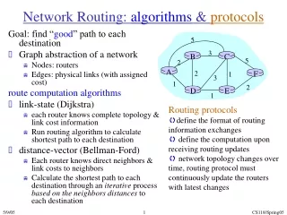
Routing protocols : distance-vector and link state • Distance –vector • RIP,IGRP,EIGRP,BGP • vector = direction/course • A distance vector=is a course that also includes information on the length of the course. • A hop count specifies the number of routers that must be traversed to reach a destination network. • A DV maintains a routing table that lists known networks and the distance to each network. • A DV sends its routing table to all neighbors. Revised on sem 2 2013-14-AAB2013
Distance-Vector Routing • Router maintains a routing table that lists known networks, direction (vector) to each network, and the distance to each network • Router periodically (every 30 seconds, for example) transmits the routing table via a broadcast packet that reaches all other routers on the local segments • Router updates the routing table, if necessary, based on received broadcasts Revised on sem 2 2013-14-AAB2013
Distance-Vector Routing Tables Router A Router B 172.16.0.0 192.168.2.0 Router A’s Routing Table Router B’s Routing Table Revised on sem 2 2013-14-AAB2013
Link-State Routing • LS do not exchange routing tables. • LS exchange information about the links to which a router is connected. • Each router learns enough info about links in the internetwork from peer routers to build its own routing table. • Exp: OSPF, IS-IS • Routers send updates only when there’s a change • Router that detects change creates a link-state advertisement (LSA) and sends it to neighbors • Neighbors propagate the change to their neighbors • Routers update their topological database if necessary Revised on sem 2 2013-14-AAB2013
LS..continue.. • All LS uses a shortest-path first algorithm- Dijkstra algo to determine how to reach destination networks. • LS require more router CPU power and memory. • Work with less bandwidth, less prone to loops and converge more quickly. Revised on sem 2 2013-14-AAB2013
Distance-Vector Vs. Link-State • Distance-vector algorithms keep a list of networks, with next hop and distance (metric) information • Link-state algorithms keep a database of routers and links between them • Link-state algorithms think of the internetwork as a graph instead of a list • When changes occur, link-state algorithms apply Dijkstra’s shortest-path algorithm to find the shortest path between any two nodes Revised on sem 2 2013-14-AAB2013
Choosing Between Distance-Vector and Link-State Revised on sem 2 2013-14-AAB2013
Interior Versus Exterior Routing Protocols • Where there are used: • Interior routing protocols are used within an autonomous system: RIP, OSPF, EIGRP • Exterior routing protocols are used between autonomous systems : BGP Revised on sem 2 2013-14-AAB2013 Autonomous system (two definitions that are often used): “A set of routers that presents a common routing policy to the internetwork” “A network or set of networks that are under the administrative control of a single entity”
Routing Protocol Metrics • Metric: the determining factor used by a routing algorithm to decide which route to a network is better than another • Examples of metrics: • Bandwidth - capacity • Delay - time • Load - amount of network traffic • Reliability - error rate • Hop count - number of routers that a packet must travel through before reaching the destination network • Cost - arbitrary value defined by the protocol or administrator Revised on sem 2 2013-14-AAB2013
Hierarchical vs nonhierarchical rp • Some RP does not support hierarchy. • RP that support hierarchy assign different tasks to routers and group routers in areas, AS or domain. • In this arrangement, some routers communicate with local routers in the same area and other routers have job of connecting areas, domain or AS. Revised on sem 2 2013-14-AAB2013
Classful VS classless RP Revised on sem 2 2013-14-AAB2013
Classful routing Revised on sem 2 2013-14-AAB2013
Classless routing Revised on sem 2 2013-14-AAB2013
Dynamic vs static and default routing • A static route – is a route that is manually configured and does not rely on updates from a routing protocol. • Are used to connect a stub network – SN resides on the edge of an internetwork and is not used a transit path for traffic trying to get anywhere else. • Exp o SN- a company that connects to the internet via a single link to an ISP. ISP can have a static route to the company. Not necessary to run a RP between the company and the ISP. Revised on sem 2 2013-14-AAB2013
Continue.. • Disadvantage of SR – the amount of administration that might be required • Advantages: • Reduce bandwidth usage • Easy to troubleshoot • Most ISPs have many static routes in their routing tables to reach their customers’ networks. Revised on sem 2 2013-14-AAB2013
Default route • Is a special type of static route that is used when there is no entry in the routing table for a destination network. • Also known as “the route of last resort” • A customer may design a default route to go to the ISP’s router. Revised on sem 2 2013-14-AAB2013
Comparison between dynamic and static routing Revised on sem 2 2013-14-AAB2013 Ref: http://ptgmedia.pearsoncmg.com/
Static routing advantages and disadvantages Revised on sem 2 2013-14-AAB2013
Dynamic IP Routing Protocols Revised on sem 2 2013-14-AAB2013
Role of dynamic RP Revised on sem 2 2013-14-AAB2013 Ref: http://ptgmedia.pearsoncmg.com/
The operations of a dynamic RP (in general): • The router send and receives routing messages on its interfaces. • The router shares routing messages and routing information with other routers that are using the same routing protocol. • Routers exchange routing information to learn about remote networks. • When a router detects a topology change, the routing protocol can advertise this change to other routers. Revised on sem 2 2013-14-AAB2013 Ref: http://ptgmedia.pearsoncmg.com/
Dynamic routing advantages and disadvantages Revised on sem 2 2013-14-AAB2013 Ref: http://ptgmedia.pearsoncmg.com/
Scalability constraints for RP • Consider customer’s goals for scaling the network to a large size and investigate the following questions for each routing protocol. • Each of the following questions addresses a scalability constraint for routing protocols. • Are there any limits placed on metrics? • How quickly can the routing protocol converge when upgrades or changes occur? • LS protocols tend to converge more quickly than DV protocols. • How often are routing update? • How much data is transmitted in a routing update? • How much bandwidth is used to send routing updates? • How widely are routing updates distributed? • To neighbors, to a bounded area? To all routers in the AS? • How much CPU utilization is required to process routing updates? • Are static and default routes supported? • IS route summarization supported? Revised on sem 2 2013-14-AAB2013
Routing protocol convergence • Convergence= is the time takes for routers to arrive at a consistent understanding of the internetwork topology after a change takes place. • A change can be a network segment or router failing or a new segment or router joining the internetwork. • Convergence time is a critical design constraint. • The convergence process should complete within a few seconds for time-sensitive applications such as voice application. • Example of RP that converge quickly = LS-faster. • New DV i.e. EIGRP is fast. Revised on sem 2 2013-14-AAB2013
Recommendations for selecting a routing protocol for different layers of the hierarchical design model. • Not necessary to choose /use the same routing protocols throughout the internetwork. • Routing protocol for the core layer • The core layer should have redundant links and load sharing between equal-cost path. • Should provide immediate response if a link fail and adapt quickly to change. • RP: EIGRP,OSPF,IS-IS • Routing protocol for the distribution layer • RIPv2,EIGRP,OSPF,IS-IS • Routing protocol for the access layer • RIPv2,EIGRP,OSPF Revised on sem 2 2013-14-AAB2013
Summary • The selection of switching and routing protocols should be based on an analysis of • Goals • Scalability and performance characteristics of the protocols • Transparent bridging is used on modern switches • But other choices involve enhancements to STP and protocols for transporting VLAN information • There are many types of routing protocols and many choices within each type Revised on sem 2 2013-14-AAB2013
Review Questions • What are some options for enhancing the Spanning Tree Protocol? • What factors will help you decide whether distance-vector or link-state routing is best for your design customer? • What factors will help you select a specific routing protocol? • Why do static and default routing still play a role in many modern network designs? Revised on sem 2 2013-14-AAB2013