C: Heat Transfer Experiments
Tubular heat exchanger : heat transfer coefficient h = f(Re); purpose - heating or cooling; existing in each factory; steam-electricity co-generation system; Drying : operation; sources of heating: convection (hot air), radiation (lamp (wavelength), solar light, xenon lamp, etc).

C: Heat Transfer Experiments
E N D
Presentation Transcript
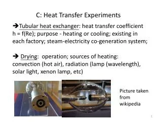
Tubular heat exchanger: heat transfer coefficient h = f(Re); purpose - heating or cooling; existing in each factory; steam-electricity co-generation system; • Drying: operation; sources of heating: convection (hot air), radiation (lamp (wavelength), solar light, xenon lamp, etc) C: Heat Transfer Experiments Picture taken from wikipedia
C1: Tubular Heat Exchanger • Very traditional; steam is often used as the heating source; boiler to generate steam (may need licence to operate this equipment • Overall heat transfer efficient (Uo or Ui): outside heat transfer coefficient ho, outside scale resistance Ro, tube heat transfer resistance kw, inside scale resistance Ri, inside heat transfer coefficient hi • 1/Uo = 1/ho + Ro + xw/kw (Do/Dm) + Ri (Do/Di) + 1/hi (Do/Di); Dm = log mean dia.
liquid-side film heat transfer coefficient: ho, hi; • usually assume other heat transfer resistance negligible, Q = m Cp (T out – T in) = hi Ai Tlm, with Tlm = (T2 - T1)/log (T2/T1) • we may have co-current flow, counter-current flow, etc. • In general: Nu = F(Re, Pr, L/D) • Nu = Nusselt number = h D/k =convective heat transfer coefficient/conductive heat transfer coefficient • Pr = Prandtl number = viscous diffusion rate/thermal diffusion rate = Cp/k
Many correlations proposed: e.g. Colburn j -factor: Nu = 0.023 Re^0.8 Pr^1/3 (for Pr: 0.7 – 160) • L/D < 60: entrance effect may not be neglected • A simplified correlation: hi = a V^0.8 (1+ 0.0146 T) • steam: saturated, superheating, super-cooling • vent: safety purpose • Source of heat: natural gas, diesel fuel (C8 – C21; BP: 200 – 320oC), coal, solar, waste heat, etc. • heavy oil: very viscous, > C60, high percentage of aromatics, naphthalene, high amounts of NSO; bottom product from distillation
Steam trap: to discharge condensate, non-condensable gases, with minimum loss of steam; usually automatic valve;
C2: Drying • Simultaneous heat and mass transfer • Free moisture content, meaning some water may be chemically bond to solid material, may need “dehydration” • moisture inside pores: may be slow to evaporate • from air point view: percentage humidity (relative to saturation humidity) • wet bulb temperature (adiabatic saturation temperature) vs dry bulb temperature vs dew point; • humidity chart
Wet bulb globe temperature: originally developed by US marine corps. To determine heat stress of work • WBGT = 0.7 Tw (wet bulb temp., humidity effect)+ 0.2 Tg (solar radiation) + 0.1 Td (dry bulb temp)
pre-heat period, constant rate period, falling rate period (first & second falling rate); • constant rate period reach “critical point”, then mass transfer becomes important
Dryer: with hot air drying + IR heater • For industrial operation: usually in continuous mode (on a belt), tunnel kiln, etc.
Pictures taken from: Vandenbroek International website; drum dryer • Spray drying; (others: fluidized drying, etc)