Download
1 / 22
220 likes | 240 Vues
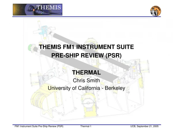
THEMIS FM1 INSTRUMENT SUITE PRE-SHIP REVIEW (PSR) THERMAL Chris Smith University of California - Berkeley. Open Issues. Two RFAs from the F1 Instrument Suite PER are still open. Responses submitted: 05/20/05 FM1 PER RFA 02: Thermal Verification Test Summary

E N D
THEMIS FM1 INSTRUMENT SUITE • PRE-SHIP REVIEW (PSR) • THERMAL • Chris Smith • University of California - Berkeley
Open Issues • Two RFAs from the F1 Instrument Suite PER are still open. • Responses submitted: 05/20/05 • FM1 PER RFA 02:Thermal Verification Test Summary • FM1 PER RFA 03: Provide Instrument Level Thermal Balance Test Plan • One RFA from Mission CDR is open. • Response Submitted: 01/10/05 • MCDR RFA 05:Adhesive Temperature Limits • One PFR opened on 09/16/05 • PFR 095:Thermal Radiator Tape Adhesive Failure • Status: Under Investigation • Needs to be resolved before Instrument Integration but not before “delivery”
FM1 PER RFA #2 • DATE SUBMITTED: 05/20/05 • TITLE: Thermal Verification Test Summary • RFA CODE: IN#1.PER.RFA 02 • REQUESTED BY: L. Fantano • SPECIFIC REQUEST: Provide summary table(s) (spreadsheet?) that summarizes pertinent information associated with the THEMIS thermal verification test program. Include at minimum the following fields: Temp Sensitive Component ID, Cold operational Predict/Case, Hot Op Predict/Case, Op Cold Test Temp, Op Hot Test Temp, # of cycles, plateau duration, Cold non-operational Predict/Case, Hot non -op Predict/Case, Non-Op Cold Test Temp, Non-Op Hot Test Temp, # of cycles, plateau duration, test date, test facility, and test procedure/report reference. • Also identify temperature sensitive components that have not been tested to limits plus appropriate margin and indicate future test plans for these items. • SUPPORTING RATIONALE (ISSUE/PROBLEM): Project needs to book keep a consolidated accounting of the thermal verification test program that is maintained by the thermal engineer to assure that all thermal verification test requirements are satisfied. • RESPONSE BY: Chris Smith • All of the summary information requested is contained in the "Thermal As-Run" worksheet of the Engineering test matrix, which is included below. Double click icon to view table • Themis ETM_TestRecord_5.xls
FM1 PER RFA #3 • DATE SUBMITTED: 05/20/05 • TITLE: Provide Instrument Level Thermal Balance Test Plan • RFA CODE: IN#1.PER.RFA 03 • REQUESTED BY: L. Fantano • SPECIFIC REQUEST: Provide instrument level thermal balance test plan. The test plan needs to describe the thermal balance test strategy, test configuration, and test procedure for each test article. The results of in-chamber thermal analyses needs to be documented that provides thermal vacuum test temperature predictions. • SUPPORTING RATIONALE (ISSUE/PROBLEM): Inadequate discussion was provided regarding instrument level thermal vacuum test plans. • RESPONSE BY: Chris Smith
FM1 PER RFA #3 Response • Per phone conversations on 5/12, here is a sketch of the thermal balance plans for the instruments. • AXB: The AXB will be placed in a sheet metal thermal control box with three zones to simulate the top deck, bottom deck, and spacecraft interior. The chamber will be used to provide the environmental fluxes for the portions of the AXB that project outside the spacecraft simulation box. The goal of this test is general model correlation by helping determine the isolation at the top and bottom deck interfaces, to determine the thermal conductivity of the carbon fiber tube, and to determine the effectiveness of the blanket. • SPB: The SPB will be placed in a sheet metal thermal control box with four zones to simulate the top deck, bottom deck, side solar panel and spacecraft interior. The chamber will be used to provide the environmental fluxes for the portions of the SPB that project outside the spacecraft simulation box. The goal of this test is general model correlation by helping determine the isolation to the spacecraft deck, the effectiveness of the MLI insulation, and to determine the heat leak through the open SPB doors. • IDPU/ESA/SCM Preamp: These will be placed in a sheet metal thermal control box with four zones to simulate the top deck, bottom deck, side solar panel and spacecraft interior. The chamber will be used to provide the environmental fluxes for the portions of the ESA that project outside the spacecraft simulation box. The goal of this test is general model correlation by helping determine the isolation to the spacecraft deck, radiative coupling to a simulated spacecraft interior and the total emissivity of the ESA to the chamber.
FM1 PER RFA #3 Response • FGM Sensor: The FGM sensor will be tested on its boom to determine the effectiveness of the instrument MLI and mounting isolation. A test heater will provide the flux through the MLI and interface. • SCM Sensor: The SCM sensor will be tested on its boom to determine the effectiveness of the instrument MLI and mounting isolation. A test heater will provide the flux through the MLI and interface. • FGM and SCM Boom Assemblies: The full SCM and FGM boom assemblies will be tested to determine their conductive and radiative coupling to the top deck when in the stowed position. The chamber base plate will simulate the flux from the top deck and the chamber will provide the space environment. • SST: The SST will be placed on the chamber base plate that will simulate the spacecraft corner panel. The chamber walls will provide the space environment. The goal of this test is general model correlation by helping determine the isolation to the spacecraft corner panel, the effective emissivity of the SST, and the isolation between the internal AmpTek pre-amps and the external casing.
Mission CDR RFA #5 • DATE SUBMITTED: 01/10/05 • TITLE: Adhesive Temperature Limits • RFA CODE: MCDR.RFA 05 • REQUESTED BY: L. Fantano • SPECIFIC REQUEST: Identify all adhesives employed in the various instrument designs. Determine temperature requirements associated with each. Verify that adhesive temperature limits are not violated and that appropriate adhesives have been chosen by the instrument leads. • SUPPORTING RATIONALE (ISSUE/PROBLEM): Adhesive temperature limits need to be satisfied. • RESPONSE BY: Christopher Smith / Paul Turin
Mission CDR RFA #5 Response • Project Response: • The adhesives used are listed in the table below. The table shows the manufacturers listed temps and the temps the adhesives will see in service. Many of the epoxies used will see temperatures lower than those shown in manufacturers data. However, this data simply lists the extremes they have been tested to by the manufacturer and do not indicate possible failure at other temperatures. All Structural epoxies have been qualified by UCB to function at the predicted temperatures +/- 15 Deg C margin.
PFR 095 DATE OPENED: 09/16/05 TITLE:Thermal Radiator Tape Adhesive Failure UNITS AFFECTED : SST, ESA, FGB, SCB, AXB PROBES AFFECTED: F1, F2, F3, F4, F5 ORIGINATOR: Christopher Smith PROBLEM DESCRIPTION: The ITO coated silver Teflon tape samples with 3M 9703 adhesive failed to remain adhered to its substrate in its third thermal vacuum test. First a testing history is required to understand the development of this problem. Before deciding to use this tape and adhesive for THEMIS we tested a sample of similar tape that was being used for the STEREO project. The tape used on THEMIS differs from the STEREO sample by manufacture date, perforation pattern, and method of adhesive application. The STEREO tape sample was thermal cycled 5 times from –135 to +80 ºC and examined. All tape samples remained adhered to their substrate and the tape’s surface conductivity remained within specification. We then ordered the THEMIS specific tape from Dunmore Corp. The STEREO tape was also ordered from Dunmore but came without the adhesive. APL personnel applied the 9703 adhesive manually on site. For THEMIS we had Dunmore apply the adhesive in their factory.
PFR 095 (cont) • When the adhesive arrived it was attached to the same sample of aluminum and thermal cycled 6 times from –60 to +65 ºC. In this test all five tape samples failed to remain adhered to their substrate. • After consultation with 3M we modified our application method. The tape was applied as it was in the first test and then warmed to 50 ºC. While still warm it was re-rolled and placed back in the oven for 12 Hours @ +50 ºC. These samples were then thermal cycled 6 times from –65 to +75 ºC and all tape samples remained adhered to the substrate so the test was considered a success. However, after the tape sample sat on my desk for 21 days at room temperature, it was noticed that three of the tape edges, out of 24 edges on 6 tape samples, had pulled up. • This tape is used on the AXB, FGB and SCB Hinge, ESA, and SST. Three flight AXB units have been delivered for spacecraft integration but they all used the STEREO tape which passed qualification. We have enough excess STEREO tape to complete the remaining AXBs and FGB/SCB hinges. • Analyses Performed to Determine Cause: • In Progress • Corrective Action/ Resolution: • In Progress
Thermal Testing Outline • Cycle Accumulation • 2 cycles at instrument level - constrained by schedule • 6 cycles at instrument suite level • 4 cycles at spacecraft level • 12 cycles total for every flight instrument • 4 hour soaks at hot and cold targets • Every TVAC test is preceded by a PER where thermal engineer signs off on procedure • Status • Over 100 component TV Tests have been completed • Over 3300 hours of TV testing to date • All Flight units tested to meet GEVS requirements • As run procedures and reports are available in the EIDP
ESA/IDPU Thermal Testing Status • F1 retested following rework
FGM Thermal Testing Status • F4 FGS was not conductively mounted correctly in first qualification test. Retest was done in air at limits shown • All FGM sensors have completed thermal vac testing • No changes since F1 PER
SCM Thermal Testing Status • Thin crack in the potting for two antennas during first ETU test. Potting method reworked and retested • All SCM Sensors have completed thermal vac testing • No changes since F1 PER
SCM/FGM Boom Thermal Testing Status • F1 booms re-named F6 after anomalous vibration results • F1 SCM and FGM will get a total of 4 cycles at the instrument suite level instead of the normal 8 due to the swap of F1 and F6 • F1/F2 retested twice due to test setup errors • All FGM and SCM booms have completed thermal vac testing
SST Thermal Testing Status • F3 renamed F4 and F4 renamed F3 • F1, F2, and F3 need to be recalibrated following mezzanine board rework
EFI PreAmp Thermal Testing Status • ETU 1 Preamp had no problems but FR4 board was switched to Thermount 85 NT for ETU 2 and flight • Six ETU 2 Qual Units went through 24 cycles, Two of those units added an additional 14 cycles for a total of 38 • All EFI Pre Amps have completed thermal vac testing • No changes since F1 PER
EFI SPB Thermal Testing Status • Qual ETU motor was a motor only stress test, no problems seen • SPB design changed from flying with doors closed to flying with doors open. ETU was retested after the small modifications this required • Calibration runs done with the sphere keyreels to determine release tension at hot and cold deployment conditions • All SPB units have completed thermal vac testing • No changes since F1 PER
EFI AXB Thermal Testing Status • Due to delivery schedules to Swales we were unable to include the AXBs in the suite testing. They accumulated the 6 suite cycles on their own • All AXB units have completed thermal vac testing
Suite TV Testing • TV Plan • F2 and F3 Suites Together • 6 Suite Level TV Cycles, Survival, Cold Start and Bake-out (TQCM Monitor) • Details contained in THM-SYS-PRC-004, THEMIS INSTRUMENT SUITE Thermal Vacuum Test Procedure , Rev. B (unchanged from F1)
Instrument Suite Thermal Testing Status • Due to an error F1 Suite did not go to the cold survival temperature before turn on. All units have separately been turned on at their cold survival limit. • F2-F5 will be tested to the –60 survival temperature