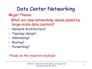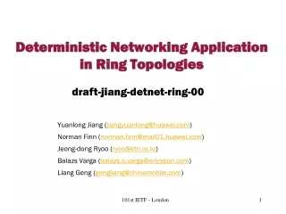
Data Center Networking Topologies
Data Center Networking Topologies. Overview. Data Center Physical Layout Data Center Network Topologies ToR vs. EoR Data Center Networking Issues Data Center Networking Requirements. Data Center Standards. ANSI/TIA-942 Telecommunications Infrastructure Standard for Data Centers

Data Center Networking Topologies
E N D
Presentation Transcript
Overview • Data Center Physical Layout • Data Center Network Topologies • ToRvs. EoR • Data Center Networking Issues • Data Center Networking Requirements
Data Center Standards • ANSI/TIA-942 Telecommunications Infrastructure Standard for Data Centers • Published 2005 – available through TIA at www.tiaonline.org • ANSI/NECA/BICSI-002 Data Center Design and Implementation Best Practices • complements TIA-942 –2007
Purpose of TIA-942 • Encourage early participation of telecom designers in data center design process • Fill a void by providing standards for planning of data centers, computer rooms, serverrooms, and similar spaces. • The standard encompasses much more thanjusttelecommunications infrastructure. • Close to half of the technical content deals with facility specifications.
Purpose of TIA-942 • Define a standard telecommunications infrastructure for data centers • Structured cabling system for data centers using standardized architecture and media • Accommodates a wide range of applications (LAN, WAN, SAN, channels, consoles) • Accommodates current and future protocols (e.g., 10+ GbE (Giga bit Ethernet) ) • Replaces unstructured point-to-point cabling that uses different cabling for different applications
Design Elements • Cabling Design • Facility Design • Network Design
Cabling and facility design • Cabling Design: • Copper and fiber cabling performance • Connectors, cables, distribution hardware • Cabling distances • Space management • Facility Design: • Data center sizing • Power distribution methodologies • Pathways and spaces • HVAC, security, operations, and administration. • Flexibility, scalability, reliability and space management
Network Design: • Support of legacy systems • Enable rapid deployment of new and emerging technologies such as 10 GbE and 10+ GbE • copper and fiber applications.
Google data center • Take a walk through a Google data center • http://www.google.com/about/datacenters/inside/streetview/
Modular Data Centers • Called Ice cube • Small: < 1 MW, 4 racks per unit • Medium: 1-4 MW, 10 racks per unit • Large: > 4 MW, 20 racks per unit • Built-in cooling, • high PUE (power usage effectiveness) 1.02 PUE = Power In/Power Used. It means cooling use 2 percent of power. Not efficiency of 0.98! • Rapid deployment
Containerized Data Center • All companies like IBM and cisco make it like this
Equipment cabinets • Three Layers: 1. Bottom: Signaling (Ethernet),2. Middle: Power and 3. Top: Fiber • Minimize patching between cabinets and racks
ANSI/TIA-942-2005 Standard • Computer Room: Main servers • Entrance Room: Data Center to external cabling • Cross-Connect: Enables termination of cables • Main Distribution Area (MDA): Main cross connect. Central Point of Structured Cabling. Core network devices • Horizontal Distribution Area (HDA): Connections to active equipment. • Equipment Distribution Area (EDA): Active Servers+Switches. • Zone Distribution Area (ZDA): Optionally between HDA and EDA. Rack, cabinet, or under floor enclosure that houses a zone outlet (ZO) or consolidation point (CP) • Backbone Cabling: Connections between MDA, HDA, and Entrance room
Data Center Network Topologies • Three levels of switches: Core, Aggregation, Access
Data Center Networks • 20-40 servers per rack • Each server connected to 2 access switches with 1 Gbps (10 Gbps becoming common) • Access switches connect to 2 aggregation switches • Aggregation switches connect to 2 core routers • Aggregation layer is the transition point between L2-switched access layer and l3-routed core layer • Low Latency: In high-frequency trading market, a few microseconds make a big difference. • Cut-through switching and low-latency specifications.
Data Center Networks (Cont) • Edge routers manage traffic between aggregation routers and in/out of data center • All switches below each pair of aggregation switches form a single layer-2 domain • Each Layer 2 domain typically limited to a few hundred servers to limit broadcast • Most traffic is internal to the data center. • Network is the bottleneck. Uplinks utilization of 80% is common. • Most of the flows are small. Mode = 100 MB. DFS (Distributed File System) uses 100 MB chunks.
ToRvsEoR • ToR: • Advantages: • Easier cabling • If rack is not fully populated unused ToR ports • DisAdvantages: • If rack traffic demand is high, difficult to add more ports • Upgrading (1G to 10G) requires complete Rack upgrade • EoR: • Disadvantages • Longer cables • Advantages: • Severs can be place in any rack • Ports can easily added, upgraded
Hierarchical Network Design • All servers require application delivery services for security (VPN, Intrusion detection, firewall), performance (load balancer), networking (DNS, DHCP(Dynamic Host Control Protocol), NTP (Network Time Protocol), FTP, RADIUS (Remote Access Dial-In User Service serverto perform authentication ), Database services (SQL) • Stateful devices (firewalls) on Aggregation layer
Data Center Access Layer Design • 4 Possibilities: • Looped Triangle • Looped Square • Loop Free U • Looped Free Inverted U
Data Center Networking Issues (Cont) • Under-utilization. Even when multiple paths exist only one is used. • ECMP (Equal Cost Multipath) is used by routers to spread traffic to next hops using a hash function. However, only 2 paths exist.
DCN Requirements • Needs to be Scalable, Secure, Shared, Standardized, and Simplified (5 S's) • Converged Infrastructure: Servers, storage, and network have to work together • Workload Mobility: Large L2 domains required for VM mobility • East-West Traffic: Significant server-to-server traffic as compared to server to user. One Facebook request required 88 cache looks, 35 database lookups, 392 backend RPC calls. Intranet traffic 935X the http request/response • Storage traffic on Ethernet: Congestion management on Ethernet
4-Post Architecture at Facebook • Each rack contains a rack switch (RSW) with up to forty-four 10G downlinks and four or eight 10G uplinks (typically 10:1 oversubscription) one to each cluster switch (CSW) • A cluster is a group of four CSWs and the corresponding server racks and RSWs
4-Post Architecture at Facebook (cont) • Each CSW has four 40G uplinks (10G×4), one to each of four “FatCat” aggregation switches (typically 4:1 oversubscription). • The four CSWs in each cluster are connected in an 80G protection ring (10G×8) and the four FC switches are connected in a 160G protection ring (10G×16) • network failures used to be one of the primary causes of service outages. The additional redundancy in 4-post has made such outages rare. • traffic that needed to cross between clusters used to traverse expensive router links. The addition of the FC tier greatly reduced the traffic through such links. • All tiers are switched and not routers • Ref: N. Farringon and A. Andreyev, “Facebook’s Data Center Network Architecture,” 2013 IEEE Optical Interconnect Conference, • http://nathanfarrington.com/papers/facebook-oic13.pdf
main disadvantages of 4-post • A CSW failure reduces intra-cluster capacity to 75% • The cluster size is dictated by the size of the CSW • Large switches are produced in smaller volumes from fewer manufacturers • Large switches are often oversubscribed internally, meaning that not all of the ports can be used simultaneously • Large switches are often very proprietary. This can lead to months and years between bug fixes
Fat-tree • Fat-Tree networks were proposed by Charles E. Leiserson in 1985. Such network is a tree, and processors are connected to the bottom layer. • The distinctive feature of a fat-tree is that for any switch, the number of links going down to its siblings is equal to the number of links going up to its parent in the upper level • Therefore, the links get “fatter” towards the top of the tree, and switch in the root of the tree has most links compared to any other switch below it:
For enterprise networks • However, for enterprise networks that connect servers, commodity (off-the-shelf) switches are used, and they have a fixed number of ports. Hence, the design of fat-tree, where the number of ports varies from switch to switch, is not very usable. • Therefore, alternative topologies were proposed that can efficiently utilize existing switches with their fixed number of ports. • There is a controversy whether such topologies should be called fat-trees, or rather “(folded) Clos networks”, or anything else. • However, the term fat-tree is widely used to describe such topologies.
Summary • Modular data centers can be used for easy assembly and scaling • Three tiers: Access, Aggregation, Core • Application delivery controllers between Aggregation and core • Need large L2 domains • Fat-tree topology is sometimes used to improve performance and reliability