Download

1 / 17
170 likes | 277 Vues
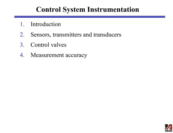
Develop a wireless system to monitor the tail rotor pitch change bearing in S-92 helicopters, eliminating wired interfaces. Focus on a long-lasting battery, noise tolerance, and high vibration resistance. The project involves electrical components, test rig, and budget allocation. The system transmits accelerometer data via Zigbee and is in the final testing phase. The PCB design, battery testing results, and budget breakdown are discussed.

E N D
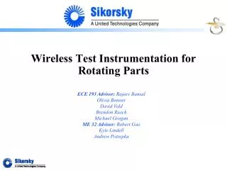
Wireless Test Instrumentation System for Rotating Parts ECE Team 167 Lawrence Bogan Jeremy Neaton Adam Bienkowski Michael Golob ME Team 29 Sean Handahl Ken Thompson Caleb Browning Paul Inguanti - Company Advisor Chris Winslow - Senior Test Engineer Rajeev Bansal - ECE Project Advisor Robert Gao - ME Project Advisor
Wireless Test Instrumentation System for Rotating Parts 2/17 Outline • 1. The Problem • 2. Project Goals • 3. Electrical Components • 4. Project Status • 5. Electronics Package • 6. Test Rig • 7. Budget ME Team 29 - ECE Team 167 Senior Design Fall 2012
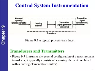
Wireless Test Instrumentation System for Rotating Parts 3/17 Problem • Collect and wirelessly transmit data pertaining to the tail rotor pitch change bearing in S-92 helicopter • Wireless link to eliminate need for wired interface between rotating and non-rotating parts • Battery must last at least 1 year, 3 years recommended • Electronics cavity is 1.5" diameter by 5.1" long • Components will be in a noisy environment with high vibrations and temperature ME Team 29 - ECE Team 167 Senior Design Fall 2012
Wireless Test Instrumentation System for Rotating Parts 4/17 Problem ME Team 29 - ECE Team 167 Senior Design Fall 2012
Wireless Test Instrumentation System for Rotating Parts 5/17 Problem ME Team 29 - ECE Team 167 Senior Design Fall 2012
Wireless Test Instrumentation System for Rotating Parts 6/17 Block Diagram ME Team 29 - ECE Team 167 Senior Design Fall 2012
Wireless Test Instrumentation System for Rotating Parts 7/17 Battery • Battery was being tested to confirm its voltage characteristics over its lifetime • Constant 20mA • Battery test stopped for unknown reasons after approximately 28 days with no significant drop in voltage • At least 13.7Ah with no voltage drop • 10.9Ah needed to last 1 year Battery Voltage Over First 28 days ME Team 29 - ECE Team 167 Senior Design Fall 2012
Wireless Test Instrumentation System for Rotating Parts 8/17 Zigbee • Zigbee has the ability to automatically append a CRC-16 to the end of the data • Extended operation mode of Zigbee: • Automatically acknowledge receipt of data with valid CRC bytes • Automatically retry transmission of data if no acknowledgement is received • Zigbee header takes 192µS to transmit regardless of data rate • Data rate for the rest of the data can be adjusted up to 2Mbps • Higher data rate reduces time that the transceiver is in transmit mode, reducing power ME Team 29 - ECE Team 167 Senior Design Fall 2012
Wireless Test Instrumentation System for Rotating Parts 9/17 Project Status • Completed: • Accelerometer data transmitted in real time over Zigbee • Accelerometer data stored in memory, and periodically transmitted over Zigbee • Range is approximately 40 feet • In Progress: • Frequency analysis of accelerometer data • Improving display of data • Moving from breadboard to PCB • Final testing of PCB with test rig ME Team 29 - ECE Team 167 Senior Design Fall 2012
Wireless Test Instrumentation System for Rotating Parts 10/17 Project Status Accelerometer Data Display ME Team 29 - ECE Team 167 Senior Design Fall 2012
Wireless Test Instrumentation System for Rotating Parts 11/17 Schematic ME Team 29 - ECE Team 167 Senior Design Fall 2012
Wireless Test Instrumentation System for Rotating Parts 12/17 PCB • PCB Dimensions are 1.3" x 2.6" • The accelerometer is mounted on the outside of the electronics cavity and connected to the main PCB in the electronics cavity • We had to use a 6 layer PCB due to the small size restrictions with many connections ME Team 29 - ECE Team 167 Senior Design Fall 2012
Wireless Test Instrumentation System for Rotating Parts 12/17 PCB ME Team 29 - ECE Team 167 Senior Design Fall 2012
Wireless Test Instrumentation System for Rotating Parts 13/17 Electronics Package Final Design Initial Concept ME Team 29 - ECE Team 167 Senior Design Fall 2012
Wireless Test Instrumentation System for Rotating Parts 14/17 Test Rig ME Team 29 - ECE Team 167 Senior Design Fall 2012
Wireless Test Instrumentation System for Rotating Parts 15/17 Budget Our budget, from Sikorsky is $4,000 and will cover the following: • Already ordered: $2655.52 • Electronic Parts - $828.50 • PCB - 1280.02 • Mechanical Parts - $547 Bearings - $220 Bearing Mounts - $106 Collar clamp - $26 Aluminum Base - $88 Shaft - $78 Hardware - $11 Shaft coupler - $18 TOTAL=$2645.52 REMAINING: $1354.48 ME Team 29 - ECE Team 167 Senior Design Fall 2012
Wireless Test Instrumentation System for Rotating Parts 17/17 Questions? (inferior competitor's helicopter) ME Team 29 - ECE Team 167 Senior Design Fall 2012