ME 381 Term Project: Dynamic Wettability Switching by Surface Roughness Effect
320 likes | 770 Vues
ME 381 Term Project: Dynamic Wettability Switching by Surface Roughness Effect. Bo He, Hang Cheng and Hongzhou Jiang. Introduction. Surface tension is the dominant force in sub millimeter length range; Applications in microfluid handling technique;

ME 381 Term Project: Dynamic Wettability Switching by Surface Roughness Effect
E N D
Presentation Transcript
ME 381 Term Project:Dynamic Wettability Switching by Surface Roughness Effect Bo He, Hang Cheng and Hongzhou Jiang
Introduction • Surface tension is the dominant force in sub millimeter length range; • Applications in microfluid handling technique; • Surface tension control by electric potential, thermal gradient and optical means.
Example: electrowetting • Principle: • Device: Ref): M.G. Pollack, et.al, Applied Physics Letter, vol.77 (11) 2000. Ref): J.Lee, et al, Sensor & Actuator, 2001.
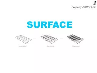
108.4 154.4 Flat surface Roughened surface Wettability shift due to roughness
Interface Interface flat rough Testing device Droplet motion across different wettability regions
Soft Lithography • Soft Lithography was first developed by M. Whitesides in Harvard in 1990s • A non-photolithographic strategy based on self-assembly and replica molding for carrying out micro- and nanofabrication. • It provides a convenient,effective, and low-cost method for the formation and manufacturing of micro- and nanostructures. • Unlike conventional lithography, these techniques are able to generate features on both curved and reflective substrates and rapidly pattern large areas.
Soft Lithography Process • In soft lithography, an elastomeric stamp with patterned reliefstructures on its surface is used to generate patterns and structures with feature size ranging form 30 nm to 100 mm. • Elastomeric polydimethylsiloxane (PDMS) is most widely used. Other materials include polyurethanes, polyimides, and cross linked phenol formaldehyde polymers • Microcontact Printing (mCP) • Replica Molding (REM) • Micromolding in Capillaries (MIMIC). • Microtransfer Molding (mTM). • Solvent-assisted Microcontact Molding (SAMIM).
An "ink" of alkanethiols is spread on a patterned PDMS stamp. The stamp is then brought into contact with the substrate. The thiol ink is transferred to the substrate where it forms a self-assembled monolayer that can act as a resistagainst etching, or as the carrier for chemical/biological functionality. Features as small as 300 nm have been made in this way. Figure 1: Schematics of Microcontact printing (mCP) processhttp://www.sims.nrc.ca/ims/ ittb/2000-02e.html Microcontact Printing (mCP).
A PDMS stamp is cast against a conventionally patterned master. Polyurethane is then molded against the secondary PDMS master. In this way, multiple copies can be made without damaging the original master. The technique can replicate features as small as 30 nm Replica Molding (REM) http:// www.engr.washington.edu/~cam/CAMreplicamolding.html
Micromolding in Capillaries (MIMIC). Continuous channels are formed when a PDMS stamp is brought into conformal contact with a solid substrate. Capillary action fills the channels with a polymer precursor. The polymer is cured and the stamp is removed. MIMIC is able to generate features down to 1 µm in size Micromolding in Capillaries (MIMIC) Figure 3: Schematics of Micromolding in Capillaries (MIMIC). http://www.engr.washington.edu/~cam/CAMmimic.html
Example: Microcontact printing (mCP) reveals its application with micro fluidic networks (mFN) to pattern substrates with proteins (a) Fluorescence from a patterned immunoglobulin G monolayer on a glass slide created by mCP; (b) AFM image of a small stamped feature of antibodies on a silicon wafer; (c) A neuron and its axonal outgrowth on affinity-stamped axonin-1; (d) Repetitive stamping of different proteins onto the same plastic substrate; (e) Water condensation pattern on micropatterned albumin forming droplets of ~2 mm in diameter; (f) Fluorescence micrograph of different proteins patterned by mFN Figure 4: Microcontact printing (mCP) and microfluidic networks (mFN) are powerful techniques to pattern substrates with proteins. Examples of applications of these techniques http://www.snf.ch/nfp/nfp36/progress/ bosshard.html
Limitations and Unsolved problems • PDMS DeformationPDMS shrinks upon curing and swells in a number of non-polar solvents, which makes it difficult for high resolution molding. • Difficulty of Registrationthe elasticity and thermal expansion of PDMS limit the accuracy in registration across a large area and application in multilayer fabrication • Limited Aspect RatioThe softness of an elastomer limits the aspect ratio of microstructures in PDMS
PDMS SU8 PR Thin PDMS (a) Si (e) (b) PDMS (f) PDMS (c) Top of pillar (g) Bottom substrate (d) Air path Si PDMS Si PDMS Device fabrication
ON OFF Device testing • Membrane actuation by pneumatic means.
Device testing • Roughness switch. Actuated Released
Top glass Superhydrophobic Medium hydrophobic Problems and future direction • Penumatic cannot provide enough membrane deflection; • Addressable control: electrostatic actuation.
Finite Element Simulations • Pneumatic Actuation Case Objective: To diagnose the pneumatic actuated chip. Tools: ABAQUS and ANSYS. • Electrical Actuation Case Objective: To determine the applied voltage. Tools: ANSYS Multi-Physics Solver • Summary
Pneumatic Actuation Case • Modeling Dimensions: a = b = 25 µm Thickness = 1 µm Target z = 25 µm. Boundary Conditions Material Properties: E = 0.75 MPa v = 0.49
Pneumatic Actuation Case • Solutions 1. ABAQUS-S4R reduced 4 node shell element. 2. Number of elements: 281 3. Nonlinear solution tag 4. ANSYS’s verification
Electrical Actuation Case • Modeling Dimensios: a = b = 2 µm Thickness = 1 µm Gap = Target z = 3.3 µm Boundary conditions Material Properties
Electrical Actuation Case • Solutions 1. Sequentially Electrostatic-Structural coupled solver 2. ANSYS Solid122 and Solid95 elements 3. Triangular meshing and brick meshing 4. Nonlinear geometric option 5. Time step increment 6. The closest z-displacement = 3.24 µm.
Simulation summary (1) • For the Pneumatic case, our simulation results indicated fundamental limitations of the device structure. The reason is probably that the membrane above the air path collapses first once the suction is applied. This will block the path and stop the further deflection of the membrane. New design of pneumatic actuation structure is needed to provide enough membrane deflection.
Simulation summary (2) • For electrostatic case, our simulation predicted the appropriate voltage range. The structure optimization can be performed in future. The contact pair of the lower surface of the film and the upper surface of the pillar can be added to predict more accurate results. The fillet radius would be determined by the art of fabrication process. However, larger fillet radius does provide less stress concentration and less convergence problem for FEM simulation.
Conclusion • Surface tension actuation actuation mechanism in micro fluid manipulation; • Soft lithography; • A membrane device fabrication and pneumatic actuation; • Finite Element Analysis simulation, ABAQUS and ANSYS.
Acknowledgements Thanks to Prof. Espinosa and TA Yong Zhu.
Questions ? ? ?