High Voltage Setup and Monitoring for SuperModule 0 in Test Beam Configurations
This report details the high voltage (HV) setup in SuperModule 0 (SM0), which includes a robust configuration with 34 channels and a specifically assigned control and monitoring PC. The system integrates multiple crate boards, blue cables connecting to patch panels, and small cables for distributing HV to the VFE boards. Notably, the temperature interlock system from Belgrade University plays a crucial role in managing HV and LV shutdowns. Despite earlier communication issues with the OPC server, a new dedicated PC and upgraded software aim to enhance monitoring capabilities. Stability and performance data from the 2002 test beam run are discussed, with preparations for the SM0 run in 2003 already underway.

High Voltage Setup and Monitoring for SuperModule 0 in Test Beam Configurations
E N D
Presentation Transcript
HV Report F.Cavallari (INFN Roma)
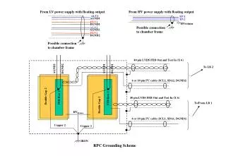
High Voltage set-up in M0’ • 2 channels each driving 50 crystals (100 APDs) • 1 Crate hosting 1 board (final system). • 1 blue cable from Crate to Patch-Panel (could connect up to 9 channels) • 2 cables from PP to FFB. • Several small cables to distribute the HV to the VFE boards. • Connection to the Temperature Interlock from Belgrade University (ramps down HV and then turns off LV)
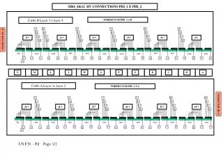
High Voltage set-up in SM0 • 34 channels • 1 Cratehosting 4 boards • 4 blue cables from Crate to Patch-Panel • 34 cables from PP to FFB • Several small cables to distribute the HV to the VFE boards. • Connection to the Temperature Interlock from Belgrade University (ramps down HV and then turns off LV) will switch off the full SuperModule
HV crate and board A1520E board SYS1527
HV Control and Monitoring PC OPC Server Labview Program
HV Control and Monitoring Program developed by Peter Cogan (Ireland)
HV Control and Monitoring Some problems of comunication between the PC and the OPC server were observed due to the PC being too old or to the software (?) now under investigation… A new PC has been bought dedicated to HV monitoring and control for next year
HV Control and Monitoring • The software will be upgraded in 2 phases: • Labview program upgrade from 2 channels to 1SM • If manpower is sufficient we will develop a test-program with PVSSII
HV stability during 2002 test-beam Monitoring problems not HV problems 2 mV HV Monitored by the crate is of course very stable
¨HV trips¨ in 2002 test-beam • During the first week of september a few HV trips occurred. • No error status was appearing from the crate. • After some investigation we thought it could be noise on the external Temperature-interlock cable (40 metres). • After disconnection of the cable no problem was observed for 3 days. • So reconnection of the cable with a T+50 Ohm. • No problem after 6/9 until end of november • Very prompt and kind intervention of CAEN experts to help understand the problem and follow the evolution.
¨HV trips¨ in 2002 test-beam • 8/8 rack cooling problem • 14/8 • 16/8 • 28/8 (2) • 30/8 • 1/9 • 2/9 • 6/9 power cut
Setting time of the APD current When HV is OFF->ON it takes approx. 10 minutes to stabilize the current P3=1/t (h-1) Setting time = few minutes Dedicated runs to understand stabilization time of the APD laser signal taken 25/11 will be analized soon
Current during the pion run in-beam current measurements
Conclusions • Very good performance of the HV system during the 2002 data-taking • In 2003 we will be ready for SM0 run