DIELECTRIC RESONATOR ANTENNA
660 likes | 1.92k Vues
DIELECTRIC RESONATOR ANTENNA. Outline. 1.Introduction 2.Why DRA 3.Excitation methods applied to DRA 4.Simple Design of DRA using circular disk shape DR 5.Design of UWB monopole-DRA 6.Factors effecting the Resonance frequency 7.Challenges 8.Conclusions 9.References. .

DIELECTRIC RESONATOR ANTENNA
E N D
Presentation Transcript
Outline 1.Introduction 2.Why DRA 3.Excitation methods applied to DRA 4.Simple Design of DRA using circular disk shape DR 5.Design of UWB monopole-DRA 6.Factors effecting the Resonance frequency 7.Challenges 8.Conclusions 9.References.
In 1939 Richmyer proved that Dielectrics can be used • as energy Radiators. • In 1960’s suitable dielectric compounds became • available • DRA was praposed by Prof S. A Long in early n1980’s • DR was usually treated as an energy storage • device rather than as a radiator. • Although open DRs were found to radiate • In 1983 first paper was published on cylindrical DRA
. • The field of wireless communication has been under going a revolutionary growth in the last decade. 2G-cellular communication (portable mobile phones) 3G- Blue tooth,LAN • The crucial component of a wireless network is the ‘Antenna’. • In the last two decades the classes of antennas investigated and extensivley reported are 1.Microstrip patch antenna 2.Dielectric Resonator Antenna
In Micro strip radiation occurs due to narrow slots • where as in DRA radiation due to whole DRA surface. • DRA has wider impedance bandwidth than micro strip • DRA avoids the surface waves Excitation methods. 1.Microstrip line feeding 2.Coaxial probe feeding 3.Aperture Coupling
Why DRA • As the frequency increases conductor losses increases and antenna efficiency will decreases. • Conversly only losses present in the DRA are due to imperfections in the Dielectrics which are very small compared to conductor losses. • Dielectric resonators which we are using microwave applications are having (ɛ > 20) and Q(50-500). • But for present applications Q nearly 10000. and ɛ(20-100).
A Smaller circuit sizes • And reduction of overall circuit cost • A DRA can be designed in any 3D shape Having more • geometric parameters adds more degrees of freedom • to the design. • With no conducting parts and has very small • dissipation loss so it can handle more power • High Radiation efficiency(=95%)due to absence • of conductor losses • High ɛrtolarence (1-5%) • Wide frequency range: f = 0.7 -35GHz
Some low profile shapes of the Dielectrics are as follows Ref::1
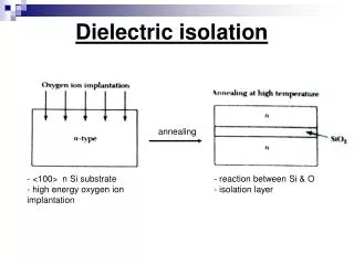
Simple design of DRA using Disk shape dielectric The dielectric resonator antenna (DRA) consists of high dielectric constant materials, high quality factors and mounted on a grounded dielectric substrate of lower permittivity. The selected dielectric disk is operating at frequency of 2.4 GHz with dielectric constant of 34.73. The micro strip transmission line has been used as a feeding line for the resonator. Ref::1 The antenna has been fabricated on the FR-4 micro strip board using the wet etching technique. The DRA is operating at the frequency bands used for IEEE 802.11b/g Wireless LANs.
Methods to design DRA 1.Layout design or (MoM) 2.Circuit Designing using circuit simulator • The simulation process was done using Computer Simulation • technology (CST) and Microwave Studio and Microwave office. Ref::1
Analysis on simulation results have been made to get optimum results before proceeds to the fabrication process • The fabrication process was done on the FR-4 micro strip • board with a dielectric constant ( Br = 4.5), the thickness • of substrate (h = 1.6 mm) and loss tangent (tan &=0.019) using the wet etching technique
This method is attractive due to the low cost and eases of fabrication, since there is no requirement to etch both sides of the substrate, Ref::1
An important parameter for DRA is its resonant frequency • The Resonance frequency of a dielectric resonator depends on • dimensions of resonator and dielectric constant. Ref::1
DRA size decreases as the dielectric constant increases • Wavelength of the dielectric resonator is important • because from this wave length the dimensions of • Micro strip circuit can be designed. • The dielectric resonator antenna is a resonant circuit • that is able to store electromagnetic fields with a • minimum loss of energy within the resonator i.e. a • cavity with a high-unloaded quality factor, QU.
QUrefers to the Internal energy dissipation where as the External quality factor QE refers to energy dissipation on outside . • The loaded Q, , QL, takes into account all causes of energy dissipation and is given by
Results • The comparison between simulation and measurement result is as shown that the simulation and measurement give the comparable result. The return loss for simulation is between -23 and -32 dB at frequency 2.4149 GHz. • Return loss = pin(dB) – pout(dB) • The measurement result gives the return loss of -19 dB at frequency 2.38 GHz. Ref::1
Comparision Ref::1 • A good antenna should indicate a return loss of less than -10 dB, which indicates that the antenna absorbs more than 90% of the fed power.
Radiation Pattern. • The HPBW for H-plane is 77.72° greater than measurement, which are 72°. • The HPBW for E-plane is 46.61° for measurement and 45 °for simulation respectively. Ref:;1
Design of UWB Monopole-Dielectric Resonator Antenna. • The antenna is found to exhibit the ultra-wide bandwidth when it comprising of a quarter-wave monopole and a dielectric-resonator antenna of two cylindrical cavities • It is observed that at the lower frequencies, antenna behave • Like a conventional monopole antenna; at middle frequencies, the mutual coupling of the monopole and the dielectric-resonator with • two cylindrical cavities turns to be stronger, and at the higher • frequencies, such a mutual coupling becomes the maximum
Design : Ref::2
In the practical design and we need to make variations of all the parameters to make an optimized design in terms of the ultra-wide bandwidth of S-parameters. (a) Probe Length: The length l of the monopole (probe) essentially controls the lower resonance frequency of the model, ideal probe is found to be 21.7mm. (b) Size of DR Element: Predominantly, this is referring to a few parameters’ h’, ‘a’ and ɛr. These parameters are mutually-related to provide the upper resonance frequency (c) Annular Radii of DR: The annular radii b and d are separated into top and bottom portion of the DR structure respectively. The effects of b is mainly on the upper resonance frequency
the air gap between the outer monopole and the annular radius b, should be λl/100 • The air gap should be chosen such that the coupling between the monopole and DR structure will be maximum • Annular radius ‘d’, resulting in an improvement of the • return loss upper frequency range. Optimized values are as follows Ref::2
The identified physical parameters will be input into HFSS software to generate the simulated results Both simulated and Measured results are very similar Ref::2 • As the operating Frequency changes the return loss will change from above graph
Current Distributions a) On DR Ref::2
b) On Monopole Ref::2
There are a few factors affecting the Resonance frequency. 1 Adhesives for Dielectric Resonator. 2. Environment. 3. Equipment. 4. Fabrication process. Challenges • In order to be suitable for GSM and PCS antenna applications, • εr needs to be <30, • DRAs with εr <30 at frequencies below 3GHz are generally too • large to be used for handsets • Absorption of RF power from handset antennas by the heads of users.
References 1. ‘DIELECTRIC RESONATOR ANTENNAS’ BYK.M.Luk and K. W. Leung university of Hong Kong. 2. ’Dielectric resonator Antenna for wireless Applications’ IEEE international RF and Microwave proceedings December 2008. 3. ’Analysis and Design of UWB Monopole-DRA’ proceedings of IEEE International conference on Ultra-wideband.