DIELECTRIC BEHAVIOR
DIELECTRIC BEHAVIOR A dielectric material is one that is electrically insulating (nonmetallic) and exhibits or may be made to exhibit an electric dipole structure ; that is, there is a separation of positive and negative electrically charged entities on a molecular or atomic level.

DIELECTRIC BEHAVIOR
E N D
Presentation Transcript
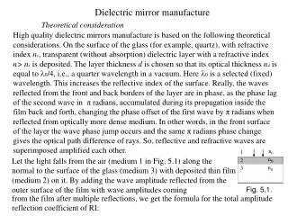
DIELECTRIC BEHAVIOR A dielectric material is one that is electrically insulating (nonmetallic) and exhibits or may be made to exhibit an electric dipole structure; that is, there is a separation of positive and negative electrically charged entities on a molecular or atomic level. This concept of an electric dipole was introduced in Section 2.7. As a result of dipole interactions with electric fields, dielectric materials are utilized in capacitors. 18.18W CAPACITANCE When a voltage is applied across a capacitor, one plate becomes positively charged, the other negatively charged, with the corresponding electric field directed from the positive to the negative. The capacitance C is related to the quantity of charge stored on either plate Qby1
where Vis the voltage applied across the capacitor. The units of capacitance are coulombs per volt, or farads (F). Now, consider a parallel-plate capacitor with a vacuum in the region between the plates (Figure 18.2aW).The capacitance may be computed from the relationship where Arepresents the area of the plates and l is the distance between them. The parameter 0, called the permittivity of a vacuum, is a universal constant having thevalue of 8.85 ×10¹² F/m. If a dielectric material is inserted into the region within the plates (Figure18.2bW), then
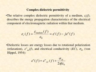
where is the permittivity of this dielectric medium, which will be greater in magnitude than 0. The relative permittivity Єr, often called the dielectric constant, isequal to the ratio which is greater than unity and represents the increase in charge storing capacity by insertion of the dielectric medium between the plates. The dielectric constant is one material property that is of prime consideration for capacitor design. The Єrvalues of a number of dielectric materials are contained in Table 18.1W. 1 By convention, the uppercase “C” is used to represent both capacitance and the unit of charge, coulomb. To minimize confusion in this discussion, the capacitance designation will be italicized, as C.
18.19W FIELD VECTORS AND POLARIZATION Perhaps the best approach to an explanation of the phenomenon of capacitance is with the aid of field vectors.To begin, for every electric dipole there is a separation between a positive and a negative electric charge as demonstrated in Figure 18.3W. An electric dipole moment pis associated with each dipole as follows: where qis the magnitude of each dipole charge and dis the distance of separation between them. In reality, a dipole moment is a vector that is directed from the negative to the positive charge, as indicated in Figure 18.3W. In the presence of an electric field which is also a vector quantity, a force (or torque) will come to bear on an electric dipole to orient it with the applied field; this phenomenon is illustrated in Figure 18.4W. The process of dipole alignment is termedpolarization.
Again, returning to the capacitor, the surface charge density D, or quantity of charge per unit areaof capacitor plate (C/m2), is proportional to the electric field. When a vacuum is present, then, the constant of proportionality being 0. Furthermore, an analogous expression exists for the dielectric case; that is,
Sometimes, Dis also called the dielectric displacement. The increase in capacitance, or dielectric constant, can be explained using a simplified model of polarization within a dielectric material. Consider the capacitor in Figure 18.5aW, the vacuum situation, wherein a charge of +Q0 is stored on the top plate and -Q0 on the bottom one.When a dielectric is introduced and an electric field is applied, the entire solid within the plates becomes polarized (Figure 18.5cW). As a result of this polarization, there is a net accumulation of negative charge of magnitude -Q’ at the dielectric surface near the positively charged plate and, in a similar manner, a surplus of +Q’ charge at the surface adjacent to the negative plate. For the region of dielectric removed from these surfaces, polarization effects are not important. Thus, if each plate and its adjacent dielectric surface are considered to be a single entity, the induced charge from the dielectric (+Q’ or -Q’) may be thought of as nullifying some of the charge that originally existed on the plate for a vacuum (-Q0 or +Q0).The voltage imposed across the plates is maintained at the vacuum value by increasing the charge at the negative (or bottom) plate by an amount -Q’, and the top
plate by +Q’. Electrons are caused to flow from the positive to the negative plate by the external voltage source such that the proper voltage is reestablished. And so the charge on each plate is now Q0+Q’, having been increased by an amount Q’.
In the presence of a dielectric, the surface charge density on the plates of a capacitor may also be represented by where Pis the polarization, or the increase in charge density above that for a vacuum because of the presence of the dielectric; or, from Figure 18.5cW, P= Q’/A, where A is the area of each plate. The units of P are the same as for D (C/m2). The polarization P may also be thought of as the total dipole moment per unit volume of the dielectric material, or as a polarization electric field within the dielectric that results from the mutual alignment of the many atomic or molecular dipoles with the externally applied field e. For many dielectric materials, P is proportional to e through the relationship
in which case r is independent of the magnitude of the electric field. Table 18.2W lists the several dielectric parameters along with their units.
SOLUTION (a) Capacitance is calculated using Equation 18.6W; however, the permittivity of the dielectric medium must first be determined from Equation 18.7W as follows: Thus, the capacitance is
(b) Since the capacitance has been determined, the charge stored may be computed using Equation 18.4W, according to (c) The dielectric displacement is calculated from Equation 18.10W, which yields (d) Using Equation 18.11W, the polarization may be determined as follows:
18.20W TYPES OF POLARIZATION Again, polarization is the alignment of permanent or induced atomic or molecular dipole moments with an externally applied electric field. There are three types or sources of polarization: electronic, ionic, and orientation. Dielectric materials ordinarily exhibit at least one of these polarization types depending on the material and also the manner of the external field application. ELECTRONIC POLARIZATION Electronic polarization may be induced to one degree or another in all atoms. It results from a displacement of the center of the negatively charged electron cloud relative to the positive nucleus of an atom by the electric field (Figure 18.6aW). This polarization type is found in all dielectric materials and, of course, exists only while an electric field is present.
IONIC POLARIZATION Ionic polarization occurs only in materials that are ionic. An applied field acts to displace cations in one direction and anions in the opposite direction, which gives rise to a net dipole moment. This phenomenon is illustrated in Figure 18.6bW.
The magnitude of the dipole moment for each ion pair pi is equal to the product of the relative displacement di and the charge on each ion, or ORIENTATION POLARIZATION The third type, orientation polarization, is found only in substances that possess permanent dipole moments. Polarization results from a rotation of the permanent moments into the direction of the applied field, as represented in Figure 18.6cW. This alignment tendency is counteracted by the thermal vibrations of the atoms, such that polarization decreases with increasing temperature.
The total polarization Pof a substance is equal to the sum of the electronic, ionic, and orientation polarizations (Pe, Pi, and Po, respectively), or It is possible for one or more of these contributions to the total polarization to be either absent or negligible in magnitude relative to the others. For example, ionic polarization will not exist in covalently bonded materials in which no ions are present.
18.21W FREQUENCY DEPENDENCE OF THE DIELECTRIC CONSTANT In many practical situations the current is alternating (ac); that is, an applied voltage or electric field changes direction with time, as indicated in Figure 18.21a. Now consider a dielectric material that is subject to polarization by an ac electric field. With each direction reversal, the dipoles attempt to reorient with the field, as illustrated in Figure 18.7W, in a process requiring some finite time. For each polarization type, some minimum reorientation time exists, which depends on the ease with which the particular dipoles are capable of realignment. A relaxation frequency is taken as the reciprocal of this minimum reorientation time.
A dipole cannot keep shifting orientation direction when the frequency of the applied electric field exceeds its relaxation frequency and, therefore, will not make a contribution to the dielectric constant. The dependence of r on the field frequency is represented schematically in Figure 18.8W for a dielectric medium that exhibits all three types of polarization; note that the frequency axis is scaled logarithmically. As indicated in Figure 18.8W, when a polarization mechanism ceases to function, there is an abrupt drop in the dielectric constant; otherwise,Єr is virtually frequency independent.Table 18.1W gave values of the dielectric constant at 60 Hz and 1 MHz; these provide an indication of this frequency dependence at the low end of the frequency spectrum.
The absorption of electrical energy by a dielectric material that is subjected to an alternating electric field is termed dielectric loss.This loss may be important at electric field frequencies in the vicinity of the relaxation frequency for each of the operative dipole types for a specific material. A low dielectric loss is desired at the frequency of utilization.
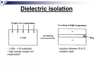
18.22W DIELECTRIC STRENGTH When very high electric fields are applied across dielectric materials, large numbers of electrons may suddenly be excited to energies within the conduction band. As a result, the current through the dielectric by the motion of these electrons increasesdramatically; sometimes localized melting, burning, or vaporization produces irreversible degradation and perhaps even failure of the material. This phenomenon is known as dielectric breakdown. The dielectric strength, sometimes called the breakdown strength, represents the magnitude of an electric field necessary to produce breakdown. Table 18.1W presented dielectric strengths for several materials.
18.23W DIELECTRIC MATERIALS A number of ceramics and polymers are utilized as insulators and/or in capacitors. Many of the ceramics, including glass, porcelain, steatite, and mica, have dielectric constants within the range of 6 to 10 (Table 18.1W). These materials also exhibit a high degree of dimensional stability and mechanical strength. Typical applications include powerline and electrical insulation, switch bases, and light receptacles. The titania (TiO2) and titanate ceramics, such as barium titanate (BaTiO3), can be made to have extremely high dielectric constants, which render them especially useful for some capacitor applications. The magnitude of the dielectric constant for most polymers is less than for ceramics, since the latter may exhibit greater dipole moments; Єrvalues for polymers generally lie between 2 and 5.These materials are commonly utilized for insulation of wires, cables, motors, generators, and so on, and, in addition, for some capacitors.