Object Design Examples with GRASP
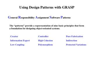
Object Design Examples with GRASP. Chapter 18 Applying UML and Patterns Craig Larman Presented By : Ajay Alegonda. OBJECTIVE. Design use-case realizations. Apply the GRASP patterns to assign responsibilities to classes.

Object Design Examples with GRASP
E N D
Presentation Transcript
Object Design Examples with GRASP Chapter 18 Applying UML and Patterns Craig Larman Presented By : Ajay Alegonda
OBJECTIVE • Design use-case realizations. • Apply the GRASP patterns to assign responsibilities to classes. • Use the UML interaction diagram notation to illustrate the design of objects.
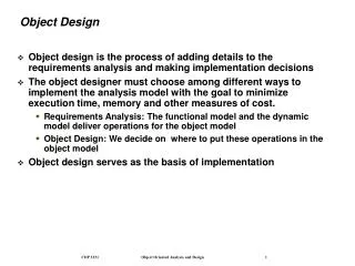
Assignment of Responsibility • The assignment of responsibilities and design of collaborations are the important and creative steps during design, either while diagramming or while programming.
Use-Case Realizations • Describes how a particular use case is realized within the design model, in terms of collaborating objects. • A designer can describe one or more scenarios of a use case. • Each of these is called a use case realization.
Use-Case Realizations (2) • UML interaction diagrams are used to illustrate use-case realizations. • Principles and Patterns can be applied during this design work. • The interaction diagrams involve message interaction between software objects whose names are sometimes inspired by the names of conceptual classes in the Domain Model, plus other classes of objects.
Domain Model Use Case • Title • … • … Operation Post-conditions Method( ) method1( ) method2( ) method3( ) Supplementary Specification Interaction Diagrams Glossary Design Class Diagram UP Artifacts Requirements Business Model Op. Contract Starting events Sys. Seq. Diagram Suggestions for names Functional requirements Item details Domain rules Non-functional requirements Design Model
Interaction Diagrams • Your System Sequence Diagram list the system events. • Create a separate diagram for each system operation under development in the current iterative step. • For each system event, make a diagram with it as the starting message. • If the diagram gets complex, split it into smaller diagrams.
Interaction Diagrams (2) • Using the contract responsibilities and post conditions and use case description as a starting point, design a system of interacting objects to fulfill the tasks. • Apply the GRASP and other patterns to develop a good design.
Interaction Diagrams and System Events • In the current iteration of PoS application, we are considering two use-cases and their associated system events: • Process Sale • makeNewSale • enterItem • endSale • makePayment • Start Up • startUp
Communication Diagram • If Communication diagrams are used to illustrate the use-case realizations, for each system event, create a Communication diagram whose starting message is the system event message.
Communication Diagram (2) • Using the controller pattern, the register class could be chosen as the controller for handling the events.
Sequence Diagrams • On the other hand, if sequence diagrams are used, it may be possible to fit all system event messages on the same diagram.
Sequence Diagrams (2) • One Sequence Diagram and system event message handling.
Multiple Sequence Diagram • However, it is often that the sequence diagram is too complex or long. • It is legal, as with interaction diagrams, to use a sequence diagram for each system event message.
Multiple Sequence Diagrams (2) • Multiple sequence diagrams and system event message handling.
Contracts and Use-Case Realizations • Using the contract responsibilities and post-conditions, and use-cases as a starting point, design a system of interacting objects to fulfill the tasks. • It may be possible to design use-case realizations directly from the use-case text. • For some system operations, contracts may have been written that add greater detail or specificity.
Example: Contract • Operation : enterItem(itemID : itemID, quantity : integer) • Cross References : Use Cases : Process Sale • Responsibilities : Enter sale of an item and add it to sale. Display the item description and price. • Post-Conditions : A new sale was created. A new sale was associated with the register. A SalesLineitem instance ‘sli’ was created.
Contract (2) • For each contract, we work through the responsibilities and post-condition state changes, and design message interactions (illustrated in the Communication diagram), to satisfy requirements.
Bypass Contracts ? • If we bypassed the contract creation we could still construct the interaction diagrams • By returning to the use-cases and thinking through what must be achieved. • However, the contracts • Organize and isolate the information in a workable format and • Encourage investigative work during the analysis phase rather than the design phase.
The Requirements are not perfect • Post-conditions are only an estimate. • However, it is essential to recognize that the previously defined use-cases and post-conditions are merely an initial best guess or estimate of what must be achieved. • Use-case and post-conditions may not be accurate. • The spirit of iterative development is to capture a reasonable degree of information during requirements analysis, filling in details during design and implementation.
Domain Model and Use-Case Realization • Some of the software objects that interact via messages in the interaction diagrams are inspired from the Domain Model. • The existing domain model is not likely to be perfect. Errors and omissions are to be expected. • You will discover new conceptual classes that were previously missed, ignore conceptual classes that were previously identified, and do likewise with associations and attributes.
Domain Model and Design Model • During interaction diagramming or programming, the developers may look to the Domain Model to name some design classes, thus creating a design with lower representational gap between the software design and the concepts of real domain to which the software is related.
Use-case Realizations for NextGen Iteration • Explore the choices and decisions made while designing a use-case realization, with objects based on the GRASP patterns. • No magic in the creation of well designed ID’s. • Construction of ID’s is made on justifiable principles.
Use-Case Realization • Notationally, the design of objects for each system event message will be shown in a separate diagram, to focus on the design issues of each. • However, they could have been grouped together on one sequence diagram.
Object Design : Contract • Name : makeNewSale() • Responsibilities : Make a new sale for a cashier to request to start a new sale, after a customer has arrived with things to buy. • Cross-References: Use Cases : Process Sale • Pre-Conditions : None • Post-Conditions : A sale instance was created. The sale instance was associated with the register Attributes of the sale instance were initialized.
Choosing the Controller Class • Our design choice involves choosing the controller for the system operation message enterItem. • By the Controller pattern, here are some choices: • Represents the overall system, device, or subsystem: Register, PoS system. • Represents a receiver or handler of all system events of a use-case scenario : ProcessSaleHandler, ProcessSaleSession.
Applying the GRASP Controller Pattern • From those choices, we choose the register as our controller. • By applying the GRASP controller pattern, we can design a use-case realization by drawing an interaction diagram which begins by sending a makeNewSale message to Register software object.
Creating a New Sale • A software sale object must be created, and the GRASP creator pattern suggests assigning the responsibility for creation to a class that aggregates, contains, or records the object to be created. • The register is also a good choice to create the sale object by the creator pattern.
Use-Case Realization Design • The design was not difficult. • But the point of its careful explanation in terms of Controller and Creator was to illustrate that the details of a design can be rationally and methodically decided and explained in terms of principles and patterns, such as GRASP.
Object Design : enterItem • Name: enterItem(itemID : itemID,quantity : integer) • Responsibilities : Enter sale of an item and add it to the sale. Display the item description and price. • Cross References : Use-Cases : ProcessSale. • Pre-Conditions : There is an underway sale. • Post-Conditions : A SalesLineItem instance ‘sli’ was created. (instance created)
Object Design : enterItem (2) • sli was associated with current sale.(association formed) • sli.quantity became quantity.(attribute modification) • sli was associated with a ProductSpecification, based on itemID match.(association formed)
Choosing the Controller Class • By the controller pattern, here are the choices. • Register or Retail System : represents the entire system(facade-controller) • Store : represents the overall business or organization. • Cashier : represents something in the real-world that is active or involved in the task. (role controller) • ProcessSaleHandler : represents an artificial handler of all system operations of a use-case. (use-case controller)
Choosing the Controller Class (2) • Applying the GRASP Controller Pattern. • Choose a façade-controller like Register. • If not taking on too many responsibilities. • The register instance is a software abstraction that represents the register.
Displaying the Item Description and Price • Because of a design principle called “Model View Separation”, it is not the responsibility of domain objects (such as a Register or Sale) to communicate with the user interface layer. • Therefore, the display of the item description and price will be ignored at this time.
Creating a new SalesLineItem • The contract post condition indicate a responsibility to create a SalesLineItem instance. • A Sale contains SalesLineItem objects. • By creator pattern, the sale is an appropriate candidate for creating line items. • GRASP creator pattern • Assign the responsibility for creation to a class that aggregates, contains or records.
Making a new SalesLineItem • Sale Creation
Finding a product specification • The SalesLineItem needs to be associated with the ProductSpecification that matches the incoming itemID. • Who should be responsible for looking up the ProductSpecification based on the itemID match? • By the Expert pattern, ProductCatalog is a good candidate for the responsibility, since it logically contains all the ProductSpecifications.
Visibility to a product catalog • Who should send the Specification message to the ProductCatalog to ask for a ProductSpecification. • Assumption: A Register and a ProductCatalog instances were created during the initial Start Up use-case, and there is a permanent connection between them. • Based on this assumption, then it is possible to the Register to send the specification message to the ProductCatalog.
Visibility to a product catalog(2) • This implies another concept, visibility. • ‘Visibility’ is the ability of one object to ‘see’ or to have reference to another object. • In order for an object to send a message to another object it must have visibility to it.
Retrieving ProductSpecification • Retrieving ProductSpecification from a database. • It is unlikely that all the Product -Specifications will actually be in memory. • They will most likely be stored in a relational or object DB and retrieved on demand. • However the issues surrounding information retrieval will be deferred for now for simplicity.
Interaction Diagram : enterItem • Object Design based on the GRASP patterns.
Message to multi-objects • Notice that although the default interpretation of a message sent to a multi-object is that it is implicitly sent to all elements of the collection/container, it may have alternatively be interpreted as a message to the collection object itself.
Object Design : endSale • The endSale system operation occurs when a cashier presses a button indicating the end of sale. • A collaborating diagram can be constructed to satisfy the post-conditions of endSale. • The GRASP patterns will be used to choose and justify the messages.
Object Design : endSale Contract • Name : endSale() • Responsibilities : Record that it is the end of entry of sale items, and display sale total. • Cross References : Use Cases : Process Sale • Exceptions : If a sale is not underway, indicate that it was an error. • Pre-Conditions : There is an underway sale. • Post-Conditions : sale.isComplete became true.
Choosing the Controller Class • Based on the Controller Pattern, as for enterItem, we will continue to use register as a controller.
Setting the Sale.isComplete attribute • The contract post-condition state: • Sale.isComplete became true. • As always, Expert should be the first pattern considered unless it is a controller or creation problem (which is not). • Who should be responsible for setting the Sale.isComplete attribute of the Sale to true. • By Expert, it should be the Sale itself.
Communication Diagram : endSale • Setting the Sale.isComplete attribute (2)