Sprinkler Irrigation
760 likes | 1.62k Vues
Sprinkler Irrigation. Definition. Pressurized irrigation through devices called sprinklers Sprinklers are usually located on pipes called laterals Water is discharged into the air and hopefully infiltrates near where it lands. Types of Systems. Single sprinkler

Sprinkler Irrigation
E N D
Presentation Transcript
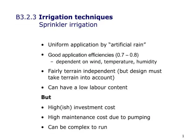
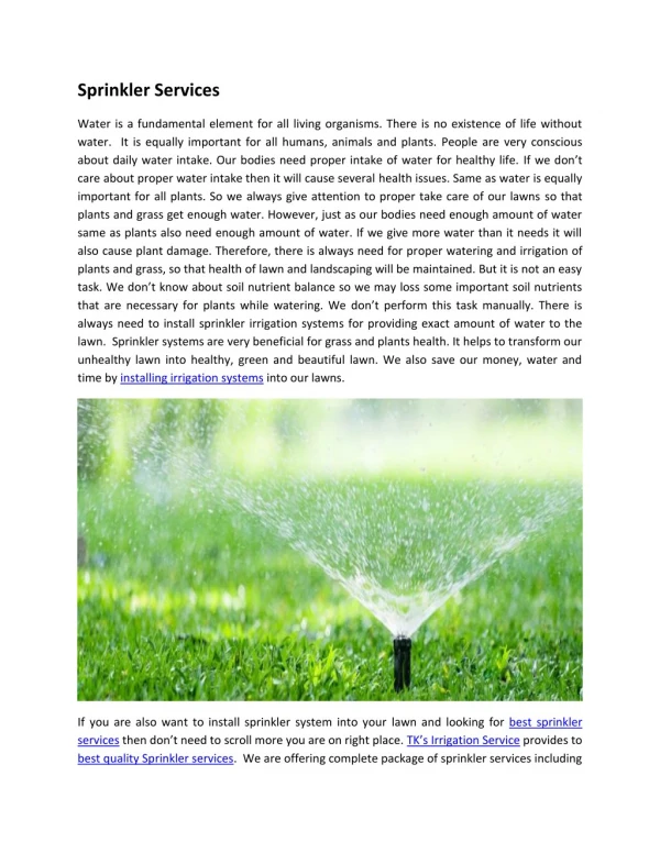
Definition • Pressurized irrigation through devices called sprinklers • Sprinklers are usually located on pipes called laterals • Water is discharged into the air and hopefully infiltrates near where it lands
Types of Systems • Single sprinkler • Only one sprinkler that is moved or automatically moves • Examples: • Single lawn sprinkler • Large gun on a trailer that is moved or automatically moves (“traveler”) • Often used for irregularly shaped areas • Pressure and energy requirements can be high
Solid Set • Laterals are permanently placed (enough to irrigate the entire area) • Laterals are usually buried, with risers or pop-up sprinklers • Easily automated and popular for turf and some ag/hort applications • Capital investment can be high
Fairway Runoff Research Plots at OSU Turf Research Farm
Periodically Moved Lateral • Single lateral is moved and used in multiple locations • Examples: • Hand-move • Tow-line/skid-tow (lateral is pulled across the field) • Side-roll (lateral mounted on wheels that roll to move the lateral) • Fairly high labor requirement
Moving Lateral • Single lateral moves automatically (mounted on wheeled towers) • Examples: • Center pivots (lateral pivots in a circle) • Linear or lateral move systems (lateral moves in a straight line) • Fairly high capital investment
System Components • Sprinklers • Devices (usually brass or plastic) with one or more small diameter nozzles • Impact sprinklers • Drive or range nozzle (hits sprinkler arm and throws water out farther) • Spreader nozzle (optional; Applies more water close to the sprinkler) • Trajectory angles • Part-circle sprinklers • Used in all types of irrigation, but especially agricultural crops
Impact Sprinklers Two-nozzle, bronze impact sprinkler Range (Drive) Nozzle Impact Arm Trajectory Angle Spreader Nozzle Bearing
Impact Sprinklers RainBird 30 RainBird 14 RainBird 70
System Components Cont’d. • Spray Pad devices • Water jet strikes a plate or pad • Pad spreads the water and may be smooth or serrated • Popular on center pivot and linear move systems
Spray Pad Sprinklers Nozzle Smooth Deflector Pad Serrated Deflector Pad
System Components Cont’d. • Gear-driven rotors (rotary heads) • Energy in the water turns a turbine that rotates the nozzle through a gear train • Typically used in large, open turf/landscape areas
System Components Cont’d. • Spray heads • Heads do not rotate • Nozzle is shaped to irrigate a certain angle of coverage • Typically used for small or irregularly shaped areas • Pop-up heads are installed flush with ground and rise when pressurized
Pop-up spray head with adjustable coverage angle from 1º - 360º
Pop-Up Spray Head Full-circle, 4-inch, Pop-up spray head w/ Funny Pipe Riser Pipe Thread-Barb Adapters “Funny Pipe” Riser
System Components Cont’d. • Laterals • Pipelines that provide water to the sprinklers • May be below, on, or above the ground • Risers • Smaller diameter pipes used to bring water from the lateral to the sprinkler • Purposes • Raises the sprinkler so that the plants won't interfere with the water jet • Reduces turbulence of the water stream as it reaches the sprinkler • Mainlines and submains • Pipelines that supply water to the laterals • May serve several laterals simultaneously
Sprinkler Performance • Discharge • Depends on type of sprinkler, nozzle size, and operating pressure • qs = discharge (gpm) • Cd = discharge coefficient for the nozzle and sprinkler 0.96 • D = inside diameter of the nozzle (inches) • P = water pressure at the nozzle (psi)
Sprinkler Performance Cont’d. • Diameter of Coverage • Maximum diameter wetted by the sprinkler at a rate that is significant for the intended use • Depends on operating pressure and sprinkler and nozzle design (includingtrajectory angle)
Overlapped Sprinklers Uniform Application: Overlap 50% of sprinkler wetted diameter Non-uniform Application: Overlap << 50% of sprinkler wetted diameter
No wind Elongated parallel pattern
Overlapped Sprinklers Contd… Dry zone
Application Rate • Rectangular sprinkler layout • Ar = water application rate (inches/hour) • qs = sprinkler discharge rate (gpm) • Sl = sprinkler spacing along the lateral (feet) • Sm = lateral spacing along the mainline (feet)
Equilateral triangular layout • S = spacing between sprinklers (feet) • Depth of water applied • Ig = Ar To • Ig = gross depth of water applied per irrigation (inches) • To = actual time of operation (hours)
Sprinkler Example Calculations A sprinkler system irrigates turf grass on a clay loam soil on a 5% slope in a 10 mph South wind. The sprinklers are 5/32”, single-nozzle sprinklers with a 23° trajectory angle operating at 40 psi. The sprinklers are arranged in a 30 ft x 50 ft rectangular spacing with the laterals running East-West. • Is the sprinkler system design satisfactory for these conditions? • How many hours should the system operate in one zone?
Sprinkler Example From Table 11.1: for 5/32” @ 40 psi, qs=4.5 gpm. From Table 11.2: for 5/32” @ 40 psi, Dw=88 ft. From Table 11.3: for 8-12 mph wind, Sl max=40% Dw, Sm max=60% Dw 0.4 x 88=35.2 > Sl =30 ft. And 0.6 x 88=52.8 Sm =50 ft Sl and Sm are OK . Note: laterals are perpendicular to wind direction Ar = 96.3 (4.5) = 0.289 in/hr 30 x 50 From Table 11.4: for Turf, Recommended Max. Ar = 0.15-0.35 in/hr Ar is within the recommended range and is probably OK.
Sprinkler Example From Table 2.3: AWC for clay loam= 0.15 in/in From Table 6.3: Rd for turf grass= 0.5-2.0 ft. Assume Rd= 12 in. TAW=AWC x Rd = 0.15 x 12 = 1.8 in For lawn turf assume fd max= 0.50 AD= TAW x fd max = 1.8 x 0.50 = 0.90 To prevent deep percolation loss dnAD Assume Ea = 80%, so dn=0.8 dg , or dg=dn/0.8 = 0.9/0.8=1.125 From Eq. 11.4 dg = Ar To, so To = dg/Ar = 1.125/0.289= 3.9 hrs.
Hydraulics of Laterals • Review of friction loss in a lateral: • Calculate as though it's a mainline • Then multiply by multiple outlet factor (Table 7.3) • For a large number of sprinklers, this factor is approximately equal to 0.35 • This gives total friction loss along the entire lateral length • Or use the RainBird Slide Rule to calculate
Pressure Variation Along a Lateral • General trends • Maximum at the inlet and minimum at distal end (assuming level lateral) • Linear variation in between? NO! • Equations for a level lateral Where: Pi =inlet pressure Pa =average pressure Pd =distal pressure Pl =pressure loss
Equations for a Sloping Lateral • E's are elevations of the ends of the lateral (in feet) • Above equations assume half the elevation change occurs upstream of the average pressure point, and half occurs downstream of that point (even if that assumption is not quite true, equations still work pretty well)
Allowable Pressure Variation • Based on uniformity considerations, recommendation is that (qmax - qmin) not exceed 10% of qavg • Because of square root relationship between pressure and discharge, this is the same as saying (Pmax - Pmin) should not exceed 20% of Pavg: Maximum Pl< 0.20 x Pa