Download
1 / 28
290 likes | 310 Vues
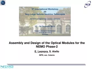
Assembly and Design of the Optical Modules for the NEMO Phase-2 E. Leonora , S. Aiello INFN, sez. Catania. NEMO Phase-2. It consists of new infrastructure at the deep-sea site of Capo Passero, Sicily, at 3500 m depth : - 100 km cable, linking the site to the shore

E N D
Assembly and Design of the Optical Modules for the NEMO Phase-2 E. Leonora, S. Aiello INFN, sez. Catania
NEMO Phase-2 It consists of new infrastructure at the deep-sea site of Capo Passero, Sicily, at 3500 m depth : - 100 km cable, linking the site to the shore - a shore station, inside the harbor of Portopalo of Capo Passero - the underwater infrastructures need to connection - the prototype of the detector : - 8 storeys tower - 2 Optical Modules (OMs) at each end ( Vertical, Horizontal) - 4 OMs per storey emanuele.leonora@ct.infn.it
Optical Module in NEMO Phase-2 ISEG TIM-CAL • A glass sphere 13” (Vitrovex): • Single large area photomultiplier : Hamamatsu 10” PMT R7081 • Optical gel : Waker SilGel 612 • μ-metal wire cage • PMT base circuit : ISEG PHQ7081-i-2m modified • FEM (Front End Module) electronic board • System for timing calibration (TIM-CAL) FEM 13” OM sketch: lateral view emanuele.leonora@ct.infn.it
13” OM Lateral view 90° turned Optical fibre 12-pin connector FEM Pressure gauge Optical Module in NEMO Phase-2 • Pressure gauge • 12-pin connector (SEACON) emanuele.leonora@ct.infn.it
Glass sphere • standard 13 inches deep-sea instrumentation vessels in borosilicate glass, produced by Vitrovex • two half spheres: ½ transparent, ½ painted black • no vacuum valve • unique penetration for the 12-pin connector emanuele.leonora@ct.infn.it
Large area photomultiplier • R7081 Hamamatsu: • 10 inch. photocathode • Standard bialkali photocathode (QE ≈ 25% @ 400nm) • 10 stages • A batch of 72 PMTs was bought and characterized Dimensions of the R7081 (Courtesy of Hamamatsu) Sketch of test apparatus Picture of a test box emanuele.leonora@ct.infn.it
Measurements on 72 R7081 Hamamatsu PMTs * Excluding one PMT with DC rate of 4093 Hz ** Excluding one PMT with type 2 after pulse fraction of 10.4%. Procedure and results of measurements were published on NIM A: S.Aiello, E. Leonora et al. Nucl. Instr. Meth. A, 614 (2010) 206-212 emanuele.leonora@ct.infn.it
ISEG PMT base PHQ7081-i-2m (modified) Main features: • Active base • +5 Volts supply (bipolar voltage supply before modification) • Cathode-1^dynode and 1^dynode-anode voltages individually controllable • Anode current max : 100 microAmpere • Power consumption : 150mW @ 2000 Volts • Modified on the ouput on NEMO requiremts Picture of the ISEG base soldered Modifications on ISEG base emanuele.leonora@ct.infn.it
Effect on the anode signal of the ISEG modification The same signal obtained with the damping resistors 1 p.e typycal signal from Hamamatsu R7081with the ISEG base - no ringing in the signal - increase in signal rise time and width - saturation starts around at 100-120 p.e. - limit about 1 nC for laser pulsed (width of 60 ps) emanuele.leonora@ct.infn.it
Optical Gel Purposes : • Optical link between PMT photocatode and glass sphere • Mechanical assembly of the PMT with the glass sphere. • Main requirements: • High trasparency • Refractive index close to that of sphere and PMT window • Good rigidity to hold the OM components with a sufficiently elastic properties to absorb shocks • Properties should be stable over 10-year period Waker SilGel 612 two components (A e B) (silicone gel) Tests on 4 different mixtures 40B/100A, 50B/100A, 60B/100A, 70B/100A emanuele.leonora@ct.infn.it
Silgel Optical Properties measurements emanuele.leonora@ct.infn.it
The selected silgel mixture Good matching with the glass sphere (n=1,48 at 350÷450 nm) for ratios 50B/100A and 60B/100A Considering optical tests and mechanical tests mixture chosen was 50B/100A emanuele.leonora@ct.infn.it
Magnetic shield • A cage of mu-metal wire was chosen as magnetic shield (ITEP, Moscow): • a hemispherical part ( 30 cm diameter, 14 cm height) • a flat part (30 cm diameter ) with a hole in its centre ( 12 cm diam.) • wire of 1 mm of diameter • pitch of 68 x 68 mm • shadow on the photocathode ≈ 5% • average shielding factor measured ≈ 4 The cage around the 10” PMT Picture of the parts of the cage emanuele.leonora@ct.infn.it
Effects of the mu-metal cage on PMT : facilities The influence of the Earth’s magnetic field, and the effect of the mu-metal cage, was studied on the 10” PMT for three different inclination: vertical downwards (0°), horizontal (90°), and tilted of 50° A dark box able to rotate with respect to vertical axes (1° step) and to change its inclination (10 °step) was realized. No magnetic materials were used in its constructions emanuele.leonora@ct.infn.it
Effects of the mu-metal cage on PMT : results • The magnetic shielding reduced strongly the variations in the PMT and even improved performance. Further information on E. Leonora, “Terrestrial Magnetic Field Effects on Large Photomultipliers” in this Workshop emanuele.leonora@ct.infn.it
Facility to assemble optical module • 2 plexiglass vacuum boxes : 1x1x1 m, 300 mbar in less than 2 minutes • Purposes: • degassing of the optical gel • closing the two hemispheres of the OM • place where gluing PMT+ metal cage on the glass sphere Picture of the vacuum boxes emanuele.leonora@ct.infn.it
OM assembly procedure: base soldering Soldering of the ISEG base on the PMT Base soldering Base positioning Mechanical Frame Wires cut off The end emanuele.leonora@ct.infn.it
OM assembly procedure: cleaning • cleaning of each element: optical paper and methyl alcohol • - inner surface of the hemi-spheres • - mu-metal cage • mu-metal cage positioned into the glass • hemisphere • 1 cycle of outgassing : • - vacuum @ 250mbar (15 mim) • - air reentry emanuele.leonora@ct.infn.it
OM assembly procedure: optical gel mixturing • mixture gel preparation 1.5 litre x OM: • 1 lltre A + 0,5 litre B at 120 giri/min. • pouring the gel into the glass hemisphere • 3 cycles of outgassing • - vacuum @ 250mbar (3 mim) • - air reentry emanuele.leonora@ct.infn.it
Picture of outgassing of the gel into the sphere 3 cycles of outgassing remove the air-bubble inside the gel . emanuele.leonora@ct.infn.it
OM assembly procedure: PMT positioning • PMT mounted on the centering cross by means of a properly support • positioning into the sphere by means of the centering cross • 3 cycles of outgassing • Polimerization of the gel @ atmosferic pressure and room temperature (12 h) Mechanical support for PMT base and centering cross PMT positioned in the glass sphere PMT mounted on the centering cross emanuele.leonora@ct.infn.it
Assembled OM Picture of an assembled hemisphere: glass, PMT, Gel, mu-metal cage, ISEG emanuele.leonora@ct.infn.it
Mechanical support for FEM electronic board and TIM-CAL The mounted FEM The mounted TIM-CAL emanuele.leonora@ct.infn.it
The 13” OM assembled with the 10” R7081 PMT Picture of the OM with FEM and TIM-CAL Picture of the optical fibre for calibration emanuele.leonora@ct.infn.it
Closure of the OM • Sealing of the OM : • hemisperes were aligned and joined • closed under-pressure at 250 mbar • external adhesive (Terostat) and tape emanuele.leonora@ct.infn.it
Test in Hyperbaric Chamber The watertight and mechanical resistance of the OM assembled was tested in the hyperbaric chamber of NEMO test site (Catania harbour) up to 350 atm container with weights to keep OM in the bottom of the chamber Results: No lack of vacuum inside OM No water inside OM No detachment of the gel emanuele.leonora@ct.infn.it
Conclusion • 13” Optical Modules with single large 10” PMT was designed • Each single component was chosen after intense phase of test: • - test on PMTs • - test on the base for Voltage Supply • - test on optical gel • - test on a mu-metal cage as magnetic shield • A definitive procedure of assembly was defined • 32 OM were assembled • Tests in Hyperbaric chamber were done • experimental OMs ( Acoustic OM, LED-Beacon, PORFIDO system) • The OMs will be deployed soon in NEMO Phase-2 emanuele.leonora@ct.infn.it