Mechanical Design CRaTER and the Electronics Assembly
200 likes | 459 Vues
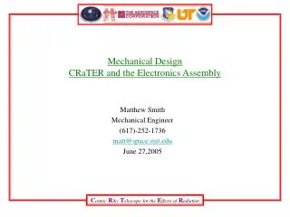
Mechanical Design CRaTER and the Electronics Assembly. Matthew Smith Mechanical Engineer (617)-252-1736 matt@space.mit.edu June 27,2005. Mechanical Design CRaTER. Crater integrates two sub-assemblies: the Telescope Assembly and the Electronics Assembly.

Mechanical Design CRaTER and the Electronics Assembly
E N D
Presentation Transcript
Mechanical Design CRaTER and the Electronics Assembly Matthew Smith Mechanical Engineer (617)-252-1736 matt@space.mit.edu June 27,2005
Mechanical Design CRaTER • Crater integrates two sub-assemblies: the Telescope Assembly and the Electronics Assembly. • The Telescope Assembly is being designed and built by The Aerospace Corporation • The Electronics Assembly is being designed and built by MIT. • MIT will integrate the two sub-assemblies and perform all functional, environmental and acceptance testing. NADIR +Z (Moon) Electronics Assembly Telescope Assembly SIM Table ZENITH -Z (Space)
Mechanical Design CRaTER Mechanical Interface Drawing 32-02003.02
Mechanical Design CRaTER Electrical/Mechanical Interface Interface Connectors J1 9 Pin D-Sub Male 311409-1P-B-12 J2 9 Pin D-sub Female 311409-1S-B-12 J3 1553, BJ3150 J4 1553, BJ3150 Mounting Hardware - Six #10-32 SHCS Surface roughness of 63 micro inches or better for interface surfaces. Mounting surfaces have Electrically Conductive finish (MIL-C-5541 Cl 3) PART OF MID DRAWING NUMBER 32-02003.02
Mechanical Design CRaTER • Design Requirements for Protoflight Hardware from the NASA Mechanical Environments and Verification Requirements Document # 431-RQMT-000012 • Must demonstrate that we meet the performance requirements after being subjected to the net C.G. limit load of 12 g’s in any direction • Must demonstrate that we meet the performance requirements after being subjected to sine vibration of 8 g’s, Protoflight level, from 5-100 Hz., (Level=1.25 X Limit Level, sweep rate= 4 Octaves/Minute/Axis.) • Must demonstrate that we meet the performance requirements after being subjected Random Vibration environment of 14.1 grms for Protoflight Hardware (Level=Limit Level +3dB, Duration= 1 Minute/Axis) • Demonstrate the ability to meet performance requirements after subjected to Protoflight acoustic environment. (OAPL=143, Level= Limit Level +3dB, Duration = 1 minute) • Natural frequency • Stowed- >35Hz required. >50Hz is recommended. • Deployed- >3Hz in the deployed configuration when hard mounted at the spacecraft interface. • Factors of Safety (FS) • Demonstrate positive Margins of Safety (MS) for all Yield and Ultimate Failures (MS= Allowable Stress(or Load)/(applied Limit Stress(Load)x FS-1) • FS for metallic Flight structures is: 1.25 for Yield and 1.4 for Ultimate • Keep mass below 5.6kg. • Excludes mounting hardware and Thermal Protection System
Mechanical Design CRaTER • Mechanical Testing • Sinusoidal Vibration 5-100Hz at 8g’s (Protoflight) 4 Octaves/minute/axis. • Random Vibration 14.1 grms (Protoflight) 60 sec/ axis. • Will perform low level sine sweep, up to 2000 Hz. Frequencies shall be verified and reported up to 200 Hz. • Acoustics testing will not be done at the instrument level. • Shock testing to be done at the Observatory Level. • CRaTER has no self induced shock.
Mechanical Design CRaTER • Mechanical Analysis, CRaTER • The fundamental frequency is estimated to be 564 Hz. • Not required to produce an FEM since our predicted first frequency is >75 Hz. • No fracture critical Items. • Will meet all Factors of Safety requirements. More analysis to be performed.
Mechanical Design of Electronics Assembly Top Cover Analog Board Electronics Enclosure Digital Board (Bottom Cover Not Shown)
Mechanical DesignElectronics Assembly • Electronics Assembly Requirements (Internal) • Have proper contact area to support Thermal and Mechanical needs • Provide safe structure to support Telescope Assembly. • Provide for mounting 2 Circuit Card Assemblies. • The Analog Board must be shielded from the Digital Board. • The Analog Board to provide direct linear path for electronics from the telescope interface to the Digital Board interface to reduce noise. • Provide adequate surface area for electrical components. • Interface to the Spacecraft to be on one side of the Electronics Enclosure. • The interface connectors to be on the Digital side of the Electronics Enclosure (separate from the Analog side) • Provide GN2 purge interface inlet and outlet ports. The Electronics Assembly will meet all these requirements.
Mechanical DesignElectronics Assembly • Preliminary Natural Frequency Estimates • Based from Steinberg Vibration Analysis for Electronic Equipment- (Simply supported on 4 sides.) • Top Cover~ 160Hz • Analog Board~ 99 Hz • Digital Board~ 114 Hz • Bottom Cover ~ 138 Hz • Further frequency, stress, and loads analysis will be performed
Mechanical DesignCRaTER • NEAR TERM TASKS • Further develop analysis on natural frequencies and stresses using SOLID WORKS and COSMOS • Continue to work the weight issue to maintain margin. • Finalize interface between Telescope Assembly and Electronics Assembly.
Mechanical Design Backup slides
Mechanical DesignMass Properties MASS PROPERTIES (FROM TIM in APRIL) grams lbs Electronics Assembly Analog board 750 1.7 Digital board 1100 2.4 ..interconnect cables A/D 30 0.1 Mechanical enclosure 1150 2.5 interconnect cables 240 0.5 Sub-Total3270 7.2 Detector Assembly Detector Board (3 total) 180 0.4 TEP Package (2 total) 172 0.4 Detector Mechanical enclosure 700 1.5 Sub-Total1052 2.3 Crater Total4322 9.5 Reserve 30% 1296 2.8 Total Max 5618 12.4