Download

1 / 43
430 likes | 452 Vues
This overview presents the assembly description, mechanical design details, and natural frequencies analysis of the CRaTER (Cosmic Ray Telescope for the Effects of Radiation) project. It includes details on the sub-assemblies, stress margins, and hardware.

E N D
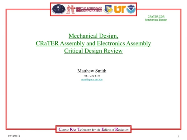
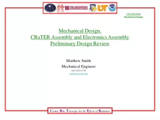
Mechanical Design, CRaTER Assembly and Electronics AssemblyCritical Design Review Matthew Smith (617)-252-1736 matt@space.mit.edu June 27, 2006
Overview Assembly Description Mechanical Design Details Mechanical Environments and Requirements Near Term Tasks Back-up slides
Assembly Description • Crater integrates two main sub-assemblies: The Telescope Assembly and The Electronics Assembly. • The Telescope Assembly is being designed and built by The Aerospace Corporation • The Analog Board is being designed by Aerospace. The Flight Analog Boards will be built by MIT • The Digital Board and Electronics Enclosure Assembly are being designed and built by MIT. • MIT will integrate the two sub-assemblies and perform all functional, environmental and acceptance testing. L13.5”x W9” x H 6” Weight 6.4Kgs max.
Assembly Description 32-10204 32-10201 32-10206 32-10203 32-10202 32-10205
Overview Assembly Description Mechanical Design Details Mechanical Environments and Requirements Near Term Tasks Back-up slides
Natural Frequencies • We put the CRaTER mock up unit on a shake table Friday June 23, 2006. We had accelerometers on the analog and digital boards(2 single axis accels), the two covers, the telescope(2 triax accels) and on the e-box(one triax and one single axis).
Natural Frequencies • Natural Frequency Estimates • From SOLID WORKS cosmos package, 2005 • CRaTER as an assembly • First frequency at 435Hz (top cover) • Dominant Frequency at 1158 Hz and 1516 Hz (main assembly) • Analog Board- 648 Hz • Digital Board- 497 Hz • Top Cover- 435 Hz • Bottom Cover – TBD (hidden in model for now) • From SOLID WORKS cosmos package, 2005, stand alone parts. • Analog Board- 195 Hz • Digital Board- 198 Hz • Top Cover- 288 Hz • Bottom Cover - 337 Hz • E-Box - 992 Hz
Natural Frequencies • Natural Frequency from Low level sine sweep, June 23, 2006 • CRaTER as an assembly Z Axis (Normal to mounting surface) • First frequency at ~ 280Hz (Bottom cover) • Dominant Frequency at ~1200 and 1500 Hz (main assembly) • Analog Board ~700 Hz • Digital Board ~410 Hz • Top Cover ~410 Hz • Bottom Cover ~280 Hz • CRaTER as an assembly X Axis • First frequency at ~ 980 Hz Second at ~1500 Hz • Crater as an assembly, Y Axis • First frequency at ~ 1200 Hz • These match very closely to the Solidworks Model as an assembly. • First frequency at 435Hz (top cover) • First Frequency of the system at 1158 Hz (main assembly) • Analog Board- 648 Hz • Digital Board- 497 Hz • Top Cover- 435 Hz • Bottom Cover – TBD (hidden in model for now)
Natural Frequencies Discussion • Discussion of the differences in the frequency analysis: • The method used for the CRaTER assembly frequency analysis is based on the contact surfaces (such as the boards to e-box, covers to e-box and telescope to e-box) as having a bonded interface, which is slightly unrealistic but yields a boundary condition for frequency analysis. • The method used for the individual analysis puts a boundary condition on either the edges of the part or their mounting holes.
Stress Margins Results • Load levels are dominated by random vibration spec. • For resonances in the Random Vibration Spec, Miles’ Equation shows 3 sigma loading on the order of 94-228 g • Q varies from 20-33. • Factors of Safety, FS, used for corresponding material (MEV 5.1) • Metals: 1.25 Yield, 1.4 Ultimate • Composite: 1.5 Ultimate • * Margin of Safety (MOS)= (Allowable Stress or Load)/(Applied Stress or Load x FS)-1
CRaTER Assembly Stresses • Dominant Frequency is 1516 Hz • Using Miles Equation, Q=20 • 3 sigma g loading= 154 g • Max Stress is 21,400 psi • MOS Y= 1.7 • MOS U= 1.8
Analog Board Resonance • First Mode 195 Hz • Dim: 5.95” x 8.43” x .10” • mass~.75 lbs • graph shows displacement
Analog Board Stresses • Using Miles Equation • Assume Q=20, • 3 sigma g loading= 93.9g • Max Stress is 15,212 psi • MOS Ult= 1.2
Digital Board Resonance • First frequency is 198 Hz. • Dim: 8.66” x 7.55” x .093” • Mass ~.80 lbs • Graph is showing displacement
Digital Board Stresses • Using Miles Equation • Assume Q=20, • 3 sigma g loading= 94.6 g • Max Stress is 11,203 psi • MOS Ult= 2.0
Top Cover Resonance • First Mode 288 Hz • Dim: 9.35” x 6.94” x .16” • mass = .43 lbs
Top Cover Stresses • Using Miles Equation, Assume Q=33, • 3 sigma g loading=106 g • Material is aluminum • Max Stress is 4246 psi • MOS Y= 9.4 • MOS U= 9.9
Bottom Cover Frequency • First frequency is 337 Hz. • Dim: 8.4” x 9.1” x .21” • Mass =.53 lbs
Bottom Cover Stresses • Using Miles Equation, • Assume Q=33, • 3 sigma g loading= 158.6 g • Max Stress is 28.7 kpsi • MOS Y= 0.5 • MOS U= 0.6
DESIGN DETAILSStress Margins, Hardware • Load levels are driven by random vibration spec • Factors of Safety used for corresponding material from 431-SPEC-000012. • Metals: 1.25 Yield, 1.4 Ultimate • Margin of Safety = (Allowable Stress or Load)/(Applied Stress or Load x FS) – 1
Overview Assembly Description Mechanical Design Details -peer review summary Mechanical Environments and Requirements Near Term Tasks Back-up slides
Significant Peer Review Comments • Observation: • The CRaTER design team should use its finite element model to determine what the expected bolt loads are and provide this information to the host spacecraft to verify that the individual bolt loads are acceptable. • CRaTER Group Response: • In process of determining loads and will add to the MID. • Observation: • The electronics structure is very stiff in the vertical direction at the six mounting feet. The flatness of the mounting surface is specified to be flat to within 0.005”. When the housing is mounted to a very stiff surface (such as a shake fixture) the feet will be displaced causing stresses within the housing to develop. If the force required to get contact at each foot exceeds the tension in the mounting screw there will be a gap between the bottom of the foot and the mounting surface. • CRaTER Group Response: • In process of determining loads and factors of safety. • Observation: • The printed circuit boards are presently listed as being stress limited due to highly localized stresses at the mounting holes. Either the fidelity of the modeling has to be increased to show that the stress concentrations are not as severe as presently shown or the mounting configuration has to be modified to make for more robust PCB mounting. • CRaTER Group Response: • In process of determining loads and factors of safety.
Significant Peer Review Comments • Observation: • The shock test levels specified in the Mechanical Systems Specification (431-SPEC-000012) apply at the payload adaptor fitting (Table 3-12) and the Deployable Interface (Table 3-11), not at the CRaTER mounting location. The levels as given are very high and may pose a significant challenge to the CRaTER instrument, particularly the detectors. Presently there are no plans to subject the instrument to shock testing prior to the testing that will be performed after integration with the host spacecraft. • Crater Group Response • We are working with the space craft group to specify a more viable shock spec. • Observation: • The detectors are sensitive to visible light as well as the cosmic ray radiation that they are intended to measure. A specification on how much visible light attenuation should be specified. The test program should include a test to verify the integrity of the light sealing. • Crater Group Response • In process of determining acceptable levels.
Other Peer Review Comments • Observation: • The CRaTER instrument has provisions to periodically purge the interior of the instrument during storage and integration activities. Presently there are no filters on the inlet or outlet ends of the purge path. • CRaTER Group Response • A 316 SS, 2 micron filter will be added on the exit side of the purge system. • A GSE filter will be placed in the fore line of the purge fitting and removed at installation to the space craft. • Observation: • The CRaTER instrument’s purge gas will be supplied by a supply line on the spacecraft that will also be supplying other instruments. Proper proportioning of the supply gas to the various instruments requires control of the back pressure and supply pressure to create the desired flow rates. This issue is not covered by the interface control document. • CRaTER Group Response: • We have determined a flow rate and will add it to the MID. • Observation: • The host spacecraft will supply electrical power for and control of a survival heater for the CRaTER payload. At this point in time there is no decision on where the heater will be located (on the S/C panel or within the CRaTER assembly) nor the power dissipation required. • CRaTER Group Response: • CRaTER has allocated space and wiring for the heater on the internal part of the Electronics Housing.
Overview Assembly Description Mechanical Design Details Mechanical Environments and Requirements (Changes from PDR) Near Term Tasks Back-up slides
Mechanical Environments - Imposed • From 431-RQMT-000012, Rev A, Environments Section 3.1. • 1 Interpolated from Table 3-1 for CRaTER at 6.4Kgs. • Red colors indicated changes from PDR
Mechanical Environments,ImposedShock Environment Table 3-12 LRO/PAF Shock Response Spectrum Table 3-13 Deployable Separation Mechanism Shock Response Spectrum
Overview Assembly Description Mechanical Environments and Requirements Mechanical Design Details Near Term Tasks Back-up slides
NEAR TERM TASKS FROM PDR • Update MICD to reflect latest configuration. • Released the MICD. • Further develop analysis on natural frequencies and stresses using SOLID WORKS and COSMOS on the complete CRaTER Assembly. • Continuing to work on all natural frequency and stress analysis. • Finalize interface between Telescope Assembly and Electronics Box Assembly. • Specify the electrical isolation material between the telescope and the E-Box. • Identify the GN2 purge system (mechanical interface to the spacecraft, internal flow, pressure measurements…) • Completed the design of purge system. • Complete the drawings for part and assembly fabrication. • Completed the fabrication drawings for the engineering unit. Assembly drawings are in process. • Define attachment points and outline for thermal blankets. • To be completed after Engineering unit is finished.
NEAR TERM TASKS-Post CDR • Low level sine sweep analysis of the Engineering Unit mock up. • Close out peer review comments. • Finish assembly of the Engineering Unit. • Complete the drawings for fabricated Flight parts and Flight assembly drawings. • Release of the Flight Electronics Box Housing drawing and purchase order by July 17, 2006. • Vibration testing of Engineering Unit. Generate procedures for Vibe tests. • Define attachment points and outline for thermal blankets.
Mechanical Environments, ImposedRandom Vibration Random Vibration Levels
Mechanical Requirements - Imposed Test Factors Table 3-16
Mechanical Requirements and Verification • From 431-RQMT-000012, Rev A, Verification Requirements Section 3.3.
Mechanical Requirements and Verification • From 431-RQMT-000012, Rev A, Frequency Requirements Section 3.2.
Mechanical Requirements- Imposed Factors of Safety These are applied to the Protoflight level testing
General Thermal Subsystem Requirements from 431-Spec-000091
Mechanical Requirements and Verification Summary • We also meet all of our internal requirements: • Have adequate contact area (.5 in^2 min) to the spacecraft to support Thermal requirements. (min is .51 in^2) • Provide safe structure, within Factors of Safety specified, to support Telescope Assembly. • Provide for mounting 2 Circuit Card Assemblies. • The Analog Board and Digital Board must be separated by an aluminum plate. • Provide means to route cable from telescope to the Analog side of the Electronics Enclosure with minimizing noise. • Electrically isolate the Electronics Enclosure from the Telescope, yet provide sufficient thermal conductance path. • Electrical Interface to the Spacecraft to be on one side of the Electronics Enclosure. • The interface connectors to be on the Digital side of the Electronics Enclosure (separate from the Analog side) • Provide GN2 purge interface inlet and outlet ports. • Follow the octave rule for natural frequency of the PWAs to the Electronics Enclosure.
Electronics Box Housing Resonance • First Mode 992 Hz • Dim: 9.40” x 9.06” x 6.15” • mass= 4.04 lbs • graph shows displacement