Download
1 / 24
240 likes | 274 Vues
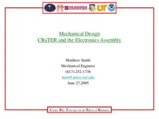
Mechanical Design, CRaTER Assembly and Electronics Assembly Preliminary Design Review. Matthew Smith Mechanical Engineer (617)-252-1736 matt@space.mit.edu. Overview Instrument and Assembly Description Mechanical Environments and Requirements Mechanical Design Details Near Term Tasks

E N D
Mechanical Design, CRaTER Assembly and Electronics AssemblyPreliminary Design Review Matthew Smith Mechanical Engineer (617)-252-1736 matt@space.mit.edu
Overview Instrument and Assembly Description Mechanical Environments and Requirements Mechanical Design Details Near Term Tasks Back-up slides
Instrument and Assembly Description • Crater integrates two main sub-assemblies: The Telescope Assembly and The Electronics Assembly. • The Telescope Assembly is being designed and built by The Aerospace Corporation • The Analog Board is being designed by Aerospace. The Flight Analog Boards will be built by MIT • The Digital Board and Electronics Enclosure Assembly are being designed and built by MIT. • MIT will integrate the sub-assemblies and perform all functional, environmental and acceptance testing.
Mechanical Environments • From 431-RQMT-000012, Environments Section 2.
Mechanical Requirements and Verification • From 431-RQMT-000012, Verification Requirements Section 3.
General Thermal Subsystem Requirements from 431-Spec-000091
DESIGN DETAILS Electronics Assembly • Natural Frequency Estimates • Based from Steinberg Vibration Analysis for Electronic Equipment- (Simply supported on 4 sides.) • Top Cover~ 199 Hz • Bottom Cover ~ 159 Hz • Analog Board~ 138 Hz • Digital Board~ 149 Hz • From SOLID WORKS model of E-Box • frequency is 702Hz at the middle plate that holds the two Circuit Card Assemblies.
DESIGN DETAILSMechanical Environments, Random Vibration • Random Vibration will drive most of the analysis • For resonances in the Random Vibration Spec, Miles’ Equation shows 3 sigma loading on the order of 75-150 g • Assume Q=10 Overall 14.1 Grms 10.0 grms
DESIGN DETAILSStress Margins, Electronics Assembly Pieces • Load levels are superceded by random vibration spec • Factors of Safety used for corresponding material from 431-SPEC-000012. • Metals: 1.25 Yield, 1.4 Ultimate • Composite: 1.5 Ultimate • Margin of Safety = (Allowable Stress or Load)/(Applied Stress or Load x FS) – 1 Note 1. From Steinberg, Vibration Analysis for Electronic Equipment Note 2. From SOLID WORKS, COSMOS excluding top and bottom covers in the model. All components have positive Margin of Safety
Mechanical Design Details • The first fundamental frequency is estimated to be 149 Hz. • Not required to produce an FEM since our predicted first frequency is >75 Hz. • All positive margins of safety. • Meet all factors of safety. • No Fracture Critical Items.
Internal Requirements for the Electronics Assembly • Derived Internal Mechanical Requirements for Electronics Enclosure • Have adequate contact area (.5 in^2 min) to the spacecraft to support Thermal requirements. • Provide safe structure, within Factors of Safety specified, to support Telescope Assembly. • Provide for mounting 2 Circuit Card Assemblies. • The Analog Board and Digital Board must be separated by an aluminum plate. • The Analog Board to provide direct linear path for electronics from the telescope interface to the Digital Board interface to reduce noise. • Provide means to route cable from telescope to the Analog side of the Electronics Enclosure. • Electrically isolate the electronics Enclosure from the Telescope, yet provide sufficient thermal conductance path. • Provide adequate surface area for mounting electrical components. • Interface to the Spacecraft to be on one side of the Electronics Enclosure. • The interface connectors to be on the Digital side of the Electronics Enclosure (separate from the Analog side) • Provide GN2 purge interface inlet and outlet ports. • Follow the octave rule for natural frequency of the PWAs to the Electronics Enclosure. The Electronics Assembly meets all internal requirements except for … • Details need to be worked out for the GN2 design. • Electrical isolation of the E-box and Telescope needs more thought.
DESIGN DETAILSElectrical/Mechanical Interface Interface Connectors J1 9 Pin D-Sub Male 311409-1P-B-12 J2 9 Pin D-sub Female 311409-1S-B-12 J3 1553, BJ3150 J4 1553, BJ3150 Mounting Hardware - Six #10-32 SHCS Surface roughness of 63 micro inches or better for interface surfaces. Mounting surfaces have Electrically Conductive finish (MIL-C-5541 Cl 3) PART OF MID DRAWING NUMBER 32-02003.02
NEAR TERM TASKS • Update MICD to reflect latest configuration. • Further develop analysis on natural frequencies and stresses using SOLID WORKS and COSMOS on the complete CRaTER Assembly. • Finalize interface between Telescope Assembly and Electronics Box Assembly. • Specify the electrical isolation material between the telescope and the E-Box. • Identify the GN2 purge system (mechanical interface to the spacecraft, internal flow, pressure measurements…) • Complete the drawings for part and assembly fabrication. • Define attachment points and outline for thermal blankets.
Material Properties • MIL-HDBK-5J • Efunda materials list via efunda.com 2 2 1 2