MuTrFEE Assembly Procedure Mechanical
MuTrFEE Assembly Procedure Mechanical. SUMMARY. Chassis assembly Sub-assemblies of Major component Assembly of FEE cross beams FEE structure assembly ASSEMBLY ORDER CABLE ROUTING Eyebrow installation. FEE NOMENCLATURE. components

MuTrFEE Assembly Procedure Mechanical
E N D
Presentation Transcript
SUMMARY • Chassis assembly • Sub-assemblies of Major component • Assembly of FEE cross beams • FEE structure assembly • ASSEMBLY ORDER • CABLE ROUTING • Eyebrow installation may 2000
FEE NOMENCLATURE • components • Main Beam: 7”aluminum channels running in Z direction at octant boundaries • Cross beams: 6” Aluminum channels running perpendicular to main beam axis. • Manifold: Inside distribution device for water and air • Spoke: Radial member at sta2 that supports the Main beam • Spoke Tab: Mounting bracket for the spoke located in the piston groove. • Spoke Brace: Member between spokes • Chassis FEE cathode housing • Amp House: FEE anode housing • Amp house mounting beam: channel at detector octant boundary used to mount the Amp House • Main Beam Assembly: 2 main beams joined back to back plus misc hangers. • Cross Beam Assembly: unit comprised of cross beams, chassis, manifolds, HV box, etc • Spider Assembly: spokes and spoke tab at sta2 used to provide radial support to the Main Beams • Spoke assembly: 2 Spokes joined back to back plus misc hangers. may 2000
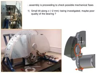
FEE chassis Cross Beams Main Beams Spoke assembly may 2000
Cathode Chassis assembly • Reference dwg #10Y226395 sheets 1-14 • general description • cold plates, air & water flow path, pcb extraction, electrical isolation , back plane. • Assembly • cold plate, pcb, clamp assembly, chassis‘square-ness’ reqmts, bolt torque, hose fittings, cable holder may 2000
FEE Sub assemblies • Spoke assembly 10Y226391 • consists of 2 spokes, 2 spoke spacers, spoke anchor, bolts • note spacer orientation • install -7 bolts before -6 bolts at spoke anchor • -5 bolts installed from both ends of spacer • torque to values shown may 2000
FEE Sub assemblies • Main Beam Assembly 10Y226391-02 • Main Beam Assy consists of 2 main beams, -4 spacer,-3 mounting bracket, { race hangers, and cable clips not detailed} • mid beam thru holes {sets of 3} used for hangers & clips • use dowel to align holes at spoke attach side. • Rework assy 107223391-04 has specific location may 2000
FEE Sub assemblies • Cross beams assembly 10y226392-01 chassis, manifolds and plumbing. • Manifolds are specific to sta2 or sta3 • Mid manifold is for air • do not route “stuff” across alignment beam path • route hoses to chassis thru cross beam holes • holes on beam flanges not used except if needed for hold-down. may 2000
FEE INSTALLATIONgeneral information • ASSEMBLE PER 10Y226391-01 • Protective covers installed on detectors • For port and octant locations see figure 1 • Start assembly at bottom-then work up. • Review utility of Scaffold • Cables and service connections routed to the racks are attached to cross beam sub- assemblies. may 2000
EYEBROW 3 4 2 Octant number 1 5 8 6 7 Figure 1 Port number may 2000
ASSEMBLY • Cable port to back plate • Spoke assembly to piston • Spoke brace • Mainbeam assembly • Cross Rib assembly sta2 then sta3 • Cable and Hose connections may 2000
6 cross beams 5 cross beams 1 Cableport Beam Mount 3 Cross brace 4 Main Beams 2 SPOKES may 2000
6 5 3 1 4 2 7 Remove cross brace may 2000
Assembly philosophy • assembly one type component in all octants, i.e. Install all mainbeams then proceed to crossbeams. [piecemeal] • Positive=frame is protected from misc loads • Positive=easier closure of frame • OR finish all installations at bottom and work around to top, i.e. finish each octant completely before proceeding to next. • Positive=more maneuver room may 2000
CableportMain-Beam Mount Bracket • INSTALL per dwg 10y226390-01 • attach Cableport dwg 10y226391-12 to the back plate • use 3/8-16 x 1 1/8 long socket head bolts • 1/2” dia holes in bracket allow for alignment • do not apply torque to attachment bolts may 2000
Spoke assy to piston • INSTALL per dwg 10y226390-01 • Attach spoke assembly 10Y226391-03 to piston • use 3/8 -16 x 2 1/2 in long bolts • 0.433 Dia bolt holes through anchor allow for alignment • do not torque bolts to spec may 2000
Spoke braces--ASSEMBLY -- • INSTALL per dwg 10y226391-01 • Install spoke braces 10y226391-15 • use 1/4 -20 bolts • braces provide stability to spokes • used as assembly tool only • will be removed may 2000
Mainbeams tospoke and cableport • Install Main Beam Assy per dwg 10y226391-01 • start assy at bottom octant • attach to the beam mount bracket. • Attach to spokes • Rework assy 107223391-04 has specific location. [Voltage bus bar routing] may 2000
Cross ribs • Install sta2 crossribs [stiffens frame] • Install per dwg 10y226391-01 • place beams in a position ‘downstream’ of final bolt on location. • Move beams upstream to align 4 ea 3/8 dia. mounting bolts. • 1/2 inch Slots allow adjustment • engage threads in mainbeams • do not torque bolts • install all octants may 2000
Cross ribs • Sta2 continued: • install all octants • IF CLOSURE PROBLEMS • Adjust {Beat and Bash} components into place • slidecrossbeams up or downstream • Install sta3 cross beams • NOW TIGHTEN ALL BOLTS. may 2000
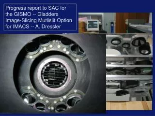
Main beam mount Main beam assembly Spoke brace Spoke assembly Spoke tab may 2000
CABLING • Starting at bottom [6 o’clock] Octant • route cabling to port location ‘D &F’ • route cabling through holes at ends of crossbeams • contain cables inside the mainbeams using clips to bolt holes in beams • bolt holes provided in side plate of the cableport/mainbeam bkt for cable holddown. • NEED CABLE PROTECTION FROM LAMPSHADE may 2000
CABLING • Detector cabling • limited space 4” at sta2 downstream det. • avoid cabling through alignment beam path • good luck may 2000
eyebrow 3 4 2 1 5 8 6 7 Octant at bottom may 2000
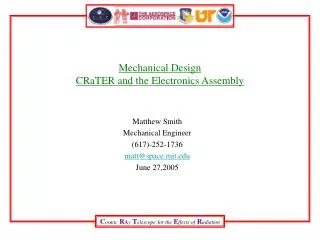
Station 1 • ASSEMBLE PER 10Y226394-01 • assemble in-situ • mount chassis to plate • mount manifold assy to plate may 2000
Installation notes • Using piecemeal assy routine may allow for extended use of scaffolding • Stow cross rib cabling within the beam height • Don’t walk on chassis • May need protection cover plate for crossbeams chassis • holes on flanges of cross beam can be used to mount a plywood shield • crossribs weight is approx 100 pounds • pay attention to bolt torque values • - remove Spoke brace • install HV bus bar: attach guide bracket to cross rib flange holes may 2000
TESTS • WATER /air circulation flow tests • check alignment beam interference may 2000
Hydraulics • Hose and fitting dwg callouts are obsolete due to psi change. • use: Material Nylon 11, 250 psi rating • 1/8” id: hose from Omega #TYNY 14126 • 3/8 id.: hose from Omega #TYNY 12375 • 1/2 id hose :braid reinforced flexible PVC tubing # TYRP 3412 may 2000
Hydraulics • Station 2-3 plumbing per 10y226399-01 • Station 1 plumbing per dwg 10y226399-02 • distribution of air and water inside the magnet from manifold to chassis uses 1/8 id dia hose • water into the magnet uses 3/8 id hose except 1/2” id hose used for delivery to station1 • water flow rate: 0.25gpm/chassis • air flow : 5.2 SCFM may 2000
Hydraulics • Fluid flow is determined by hose and orifice size • water metered by 1/8” id hose • air metered by 0.04 orifice at chassis • water psi at input regulated at 50psig • air psi input at 20psig may 2000