Download
1 / 109
1.11k likes | 1.39k Vues
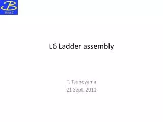
Belle II – New Collaborators Meeting. Ladder Assembly Procedure. Introduction. Overview of the assembly procedure for a Layer 6 ladder. Drawings and slides without HEPHY header are taken from Y. Onuki’s talk, presented at the 14 th B2GM in March 2013 Procedure recently tested @ IPMU

E N D
C. Irmler (HEPHY), Y. Onuki (IPMU) Belle II – New Collaborators Meeting Ladder Assembly Procedure
Introduction • Overview of the assembly procedure for a Layer 6 ladder. • Drawings and slides without HEPHY header are taken from Y. Onuki’s talk, presented at the14th B2GM in March 2013 • Procedure recently tested @ IPMU • Pictures from test assembly and new ideas added • Modification of some jigs and steps is in progress C. Irmler (HEPHY), Y. Onuki (IPMU)
Ladder Assembly – Organization • Sharing of production: • L3: Melbourne – 7 + spares (2 sensors each) • L4: Tata (at IPMU) – 10 + spares (3 sensors each) • L5: HEPHY Vienna – 12 + spares (4 sensors each) • L6: Tokyo (IPMU) – 16 + spares (5 sensors each) • Contract between Tata and IPMU is being prepared • Interest of Italian groups (ex-SuperB) to join ladder assembly M.Friedl (HEPHY Vienna)
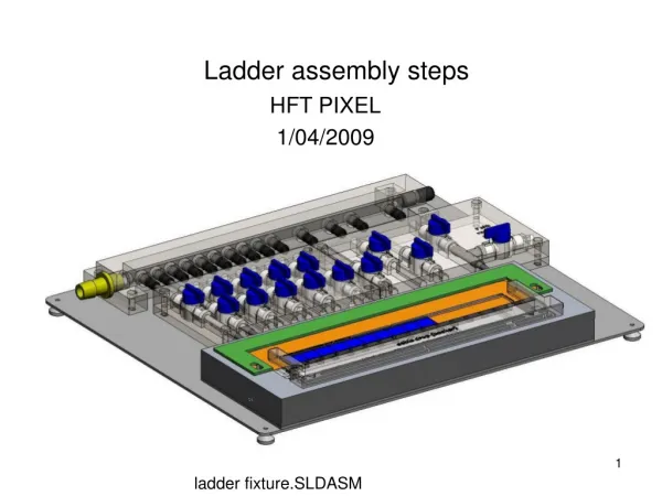
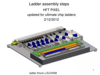
Ladder 6 with Origami Readout • Challenging procedure, several jigs needed for assembly • Master drawings & jigs prepared by Y.Onuki C. Irmler (HEPHY), Y. Onuki (IPMU)
SVDladder assembly flow Forward Backward Origami Common Procedure Origami PA gluing ←parallel (multiple sets of jigs) Place DSSDs (rectangle, trapezoidal) onto assembly bench and align them Forwardassembly Backwardassembly ←parallel (independent each other) Origami assembly Glue forward and backward sensors onto ribs time Attach Origamisensorstoribs C. Irmler (HEPHY), Y. Onuki (IPMU)
Common Proc.01: Placing DSSDstopper 3D B Table • test Table C. Irmler (HEPHY), Y. Onuki (IPMU)
Common Proc.02:Placing DSSD 3D B Table • test Table C. Irmler (HEPHY), Y. Onuki (IPMU)
Common Proc.03: Removing DSSD stopper 3D B Table • test Table C. Irmler (HEPHY), Y. Onuki (IPMU)
Common Proc.04:Aligning PA1and PA2. Dispensing glue. 3D B Table • test Table C. Irmler (HEPHY), Y. Onuki (IPMU)
Common Proc.05: Gluing PA1and PA2 3D B Table • test Table PA jigs will be modified! C. Irmler (HEPHY), Y. Onuki (IPMU)
Common Proc.06:Wire bonding after removing PA1and PA2-jig 3D B Table • test Table Mechanical QA: Visual inspection of bonding wires. C. Irmler (HEPHY), Y. Onuki (IPMU)
Common Proc.07:Assembly bench w/ FW&BW mount bracket 3D B Table BW ladder mount = Origin Table Calibrate coordinate system according to ladder mount position C. Irmler (HEPHY), Y. Onuki (IPMU)
Common Proc.08: Placing DSSD(-z) 3D B Table • test Table C. Irmler (HEPHY), Y. Onuki (IPMU)
Common Proc.09: Placing DSSD(CE) 3D B Table • test Table Repeating Common Proc.01-6 C. Irmler (HEPHY), Y. Onuki (IPMU)
Common Proc.10: Placing DSSD(+z) 3D B Table • test Table Repeating Common Proc.01-6 C. Irmler (HEPHY), Y. Onuki (IPMU)
Common Proc.11: Removing Alignment-jig 3D B Table • test Table C. Irmler (HEPHY), Y. Onuki (IPMU)
Common Proc.12: Replacing FW part. 3D B Table • test Table FW jig very close to sensor damage of edge possibleShould be done before Common Proc. 08! Screw hole to fix the hybrid board In this procedure, only replacing FW part. The other jigs never move. C. Irmler (HEPHY), Y. Onuki (IPMU)
Common Proc.13:Placing FW DSSD and FW hybrid board 3D B Table • test Table C. Irmler (HEPHY), Y. Onuki (IPMU)
Common Proc.14: Replacing BW part 3D B Table • test Table BW jig very close to sensor damage of edge possibleShould be done before Common Proc. 08! C. Irmler (HEPHY), Y. Onuki (IPMU)
Common Proc.15:Placing BW DSSDand BW hybrid board 3D B Table • test Table Screw hole to fix the hybrid board C. Irmler (HEPHY), Y. Onuki (IPMU)
Common Proc.16: Placing XYZθ-stage. Aligning DSSD(BW). 3D B Table • test Table The detail of this procedure can be seen in the slide of Shimizu at Wetzlar C. Irmler (HEPHY), Y. Onuki (IPMU)
Common Proc.17:Placing XYZθ-stage. Aligning DSSD(-z). 3D B Table • test Table The detail of this procedure can be seen in the slide of Shimizu at Wetzlar C. Irmler (HEPHY), Y. Onuki (IPMU)
Common Proc.18:Placing XYZθ-stage. Aligning DSSD(CE). 3D B Table • test Table The detail of this procedure can be seen in the slide of Shimizu at Wetzlar C. Irmler (HEPHY), Y. Onuki (IPMU)
Common Proc.19:Placing XYZθ-stage. Aligning DSSD(+z). 3D B Table • test Table The detail of this procedure can be seen in the slide of Shimizu at Wetzlar C. Irmler (HEPHY), Y. Onuki (IPMU)
Common Proc.20:Placing XYZθ-stage. Aligning DSSD(FW). 3D B Table • test Table The detail of this procedure can be seen in the slide of Shimizu at Wetzlar http://indico.mppmu.mpg.de/indico/materialDisplay.py?contribId=37&sessionId=5&materialId=slides&confId=2114 C. Irmler (HEPHY), Y. Onuki (IPMU)
Common Proc.21: Removing XYZθ-stage 3D B Table • test Table Mechanical QA: Inspection of alignment of DSSDs w/ the coordinate measuring machine. The detail of the procedure can be seen in the slide of Shimizu at Wetzlar http://indico.mppmu.mpg.de/indico/materialDisplay.py?contribId=37&sessionId=5&materialId=slides&confId=2114 C. Irmler (HEPHY), Y. Onuki (IPMU)
Independent BW and FW part assembly • Baseline procedure • Full ladder is assembled at one site • Sensors can be aligned before hybrids are attached. • Independent assembly of BW, FW and Origami parts • Origami assembly unchanged • Pre-assembled FW and BW modules has to be attached • Can we alignment complete BW and FW modules? • xyθ-stage needs to be modified in order to align sensor + hybrid at once • The following assembly procedures of BW and FW modules have to be modified, too C. Irmler (HEPHY), Y. Onuki (IPMU)
SVDladder assembly flow Forward Backward Origami Origami PA gluing ←parallel (multiple sets of jigs) Place DSSDs (rectangle, trapezoidal) onto assembly bench and align them Forwardassembly Backwardassembly ←parallel (independent each other) Origami assembly Glue forward and backward sensors onto ribs time Attach Origamisensorstoribs C. Irmler (HEPHY), Y. Onuki (IPMU)
FW&BWProc.01: Aligning PF2and PB2 3D B Table • test Table Not tested yet! C. Irmler (HEPHY), Y. Onuki (IPMU)
FW&BWProc.02: Placing PF2-jig and PB2-jig. Vacuum chucking. 3D B Table • test Table PB2-jig Two joints Two joints Not tested yet! PF2-jig PB2 and PF2-jigs have individual vacuum chambers and thus joints. One to fix the DSSD and the second for the PF(B)2. C. Irmler (HEPHY), Y. Onuki (IPMU)
FW&BWProc.03: Picking up the jigs. Dispensing glue. 3D B Table • test Table Not tested yet! Glue(Yellow) C. Irmler (HEPHY), Y. Onuki (IPMU)
FW&BWProc.04: Placing again and gluing PF2 and PB2 3D B Table • test Table Not tested yet! C. Irmler (HEPHY), Y. Onuki (IPMU)
FW&BWProc.05: Removing PB2-jig and PF2-jig 3D B Table • test Table Not tested yet! C. Irmler (HEPHY), Y. Onuki (IPMU)
FW&BWProc.06: Lifting up the assembly-bench 3D B Table • test Table FW BW Not tested yet! There are grooves for vacuum tubes at the FW and BW C. Irmler (HEPHY), Y. Onuki (IPMU)
FW&BWProc.07: Wire bonding after picked up the F(B)W parts. Table 3D B • test Table After the screwing the hybrid board, We can plug the connector. Not tested yet! Mechanical QA: Visual inspection of bonding wires Electrical QA: Readout test with APVDAQ C. Irmler (HEPHY), Y. Onuki (IPMU)
FW&BWProc.08: Lifting up the assembly-bench Table 3D B • test Table Not tested yet! C. Irmler (HEPHY), Y. Onuki (IPMU)
FW&BWProc.09: Returning the FW and BW part. Table 3D B • test Table Not tested yet! C. Irmler (HEPHY), Y. Onuki (IPMU)
FW&BWProc.10: Placing PF2-jig and PB2-jig again. Table 3D B • test Table Not tested yet! C. Irmler (HEPHY), Y. Onuki (IPMU)
FW&BWProc.11: Picking up the BW and FW parts. Table 3D B • test Table Not tested yet! C. Irmler (HEPHY), Y. Onuki (IPMU)
FW&BWProc.12: Placing PF1 and PB1. Dispensing glue on them. Table 3D B • test Table Not tested yet! There are alignment holes on the surface C. Irmler (HEPHY), Y. Onuki (IPMU)
FW&BWProc.13: Gluing PF1 and PB1. Table 3D B • test Table Not tested yet! C. Irmler (HEPHY), Y. Onuki (IPMU)
FW&BWProc.14: Removing the jigs Table 3D B • test Table Not tested yet! C. Irmler (HEPHY), Y. Onuki (IPMU)
FW&BWProc.15: Placing PF2-jig and PB2-jig again. Table 3D B • test Table Not tested yet! Rubber The after, clipping rubbers for each hybridboard to fix the hybridboard to the PF(B)2-jigs. C. Irmler (HEPHY), Y. Onuki (IPMU)
FW&BWProc.16: Picking up the parts. Wire-bonding. Table 3D B • test Table Not tested yet! Mechanical QA: Visual inspection of bonding wires Electrical QA: Readout test with APVDAQ C. Irmler (HEPHY), Y. Onuki (IPMU)
FW&BWProc.17: Returning the PF2,PB2-jigs Table 3D B • test Table Not tested yet! C. Irmler (HEPHY), Y. Onuki (IPMU)
FW&BWProc.18: Placing Slant-jig and Backward-jig. Table 3D B Table Backward-jig Slant-jig C. Irmler (HEPHY), Y. Onuki (IPMU)
FW&BWProc.19: Picking up the slant hybrid board. Table 3D B Table Picking up hybrid board with thin wire. C. Irmler (HEPHY), Y. Onuki (IPMU)
FW&BWProc.20: Moving the X-stages Table 3D B Table Moving the X-stage to the edge of hybrid board C. Irmler (HEPHY), Y. Onuki (IPMU)
FW&BWProc.21: Clamping the edge of hybridboard Table 3D B • test Table Clamping screw Clamping the edge of hybrid board with screw C. Irmler (HEPHY), Y. Onuki (IPMU)
FW&BWProc.22: Picking up the Slant-jig and Backward-jig. Table 3D B • test Table C. Irmler (HEPHY), Y. Onuki (IPMU)