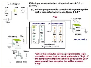
LADDER DIAGRAM
LADDER DIAGRAM. A ladder diagram is a means of graphically representing the logic required in a relay logic system. . Rail. Rung. PLC WIRING DIAGRAM. Output. Input. PLC. A. 11. 01. C. 01. 02. 20. B. 12. 02. 20. 03. 11. 20. External switches. Stored program. SCAN TIME.

LADDER DIAGRAM
E N D
Presentation Transcript
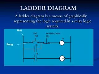
LADDER DIAGRAM A ladder diagram is a means of graphically representing the logic required in a relay logic system. Rail Rung
PLC WIRING DIAGRAM Output Input PLC A 11 01 C 01 02 20 B 12 02 20 03 11 20 External switches Stored program
SCAN TIME A PLC resolves the logic of a ladder diagram (program) rung by rung, from the top to the bottom. Usually, all the outputs are updated based on the status of the internal registers. Then the input states are checked and the corresponding input registers are updated. Only after the I/Os have been resolved, is the program then executed. This process is run in a endless cycle. The time it takes to finish one cycle is called the scan time. In some controllers the idle state is eliminated. In this case, the scan time varies depends on the program length.
Output Input begin Idle Scan cycle Resolve logic PLC Scan
PLC Ladder DiagramINSTRUCTIONS • 1) Relay, • 2) Timer and counter, • 3) Program control, • 4) Arithmetic, • 5) Data manipulation, • 6) Data transfer, and • 7) Others, such as sequencers.
LOGIC STATES • ON : TRUE, contact closure, energize, etc. • OFF: FALSE, contact open , de-energize, etc. Do not confuse the internal relay and program with the external switch and relay. Internal symbols are used for programming. External devices provide actual interface. (In the notes we use the symbol "~" to represent negation. AND and OR are logic operators. )
PROGRAMMING Normally Closed (NC) Normally Open (NO) Power flows through these contacts when they are closed. The normally open (NO) is true when the input or output status bit controlling the contact is 1. The normally closed (NC) is true when the input or output status bit controlling the contact is 0. 7
Coils Coils represent relays that are energized when power flows to them. When a coil is energized it causes a corresponding output to turn on by changing the state of the status bit controlling the output to 1. That same output status bit maybe used to control normally open or normally closed contact anywhere in the program. 8
Boxes Boxes represent various instructions or functions that are Executed when power flows to the box. Some of these Functions are timers, counters and math operations. 9
AND OPERATION C B A Rung Each rung or network on a ladder program represents a logic operation. In the rung above, both inputs A and B must be true (1) in order for the output C to be true (1). 10
OR OPERATION C A Rung B In the rung above, it can be seen that either input A or B is be true (1), or both are true, then the output C is true (1). 11
NOT OPERATION C A Rung In the rung above, it can be seen that if input A is be true (1), then the output C is true (0) or when A is (0), output C is 1.
AND and OR LOGIC PB2 R1 PB1 R1 = PB1.AND.PB2 AND PB4 PB3 R2 R2 = PB2.AND.~PB4 R1 PB1 R1 = PB1 .OR. PB2 OR PB2
COMBINED AND & OR R1 = PB1 .OR. (PB2 .AND. PB3) R1 PB1 PB3 PB2
Operation id description state explanation MSI microswitch 1 part arrive R1 output to bar code reader 1 scan the part C1 input from bar code reader 1 right part R2 output robot 1 loading cycle R3 output robot 1 unloading cycle C2 input from robot 1 robot busy R4 output to stopper 1 stopper up C3 input from machine 1 machine busy C4 input from machine 1 task complete
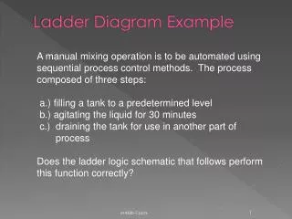
Operation • Rung 1. If part arrives and no part is stopped, trigger the bar code reader. • Rung 2. If it is a right part, activate the stopper. • Rung 3. If the stopper is up, the machine is not busy and the robot is not busy, load the part onto the machine. • Rung 4. If the task is completed and the robot is not busy, unload the machine.
Sequencial Function Chart • Sequential function chart (SFC) is a graphical language, which makes it possible to depict sequential behaviour. • One of the most important aspects of SFC is that it shows the main states of a system, all the possible changes of state and the reasons why those changes would occur. It can be used at the top level to show the main phases of a process, but it can also be used at any other lower level.
SFC A SFC consists of the following elements. A number of steps; these steps are being depicted by rectangular boxes. Each step represents a particular state of the system being controlled. At least one of these steps is the initial step, which is depicted by a rectangular box containing vertical bars. The initial step is the first step to be activated whenever a SFC is started. The steps are connected by transitions. A line between two steps depicts a transition. Each transition is associated with a condition. When a condition following an active step becomes true, this results in the next step being activated and the active step becoming deactivated. Each step is associated with some action, performed while the step is active. Actions can be described by any of the five languages defined by the IEC 1131-3 standard.
Sequential Function Chart Action Qualifiers: N non-stored, executes while the step is active R resets a store action S sets an action active L time limited action, terminates after a given period D time delayed action. P a pulse action, executes once in a step SD stored and time delayed DS time delayed and stored SL stored and time limited
A Detailed Design Process • A Detailed Design Process 1. Understand the process 2. Hardware/software selection 3. Develop ladder logic 4. Determine scan times and memory requirements
Specifications • OUTPUT-PORT POWER RATINGS • Each output port should be capable of supplying sufficient voltage and current to drive the output peripheral connected to it.
SCAN TIME This is the speed at which the controller executes the relay-ladder logic program. This variable is usually specified as the scan time per 1000 logic nodes and typically ranges from 1 to 200 milliseconds.
MEMORY CAPACITY The amount of memory required for a particular application is related to the length of the program and the complexity of the control system. Simple applications having just a few relays do not require significant amount of memory. Program length tend to expand after the system have been used for a while. It is advantageous to a acquire a controller that has more memory than is presently needed.
PLC Status Indicators • Power On • Run Mode • Programming Mode • Fault
Troubleshooting 1. Look at the process 2. PLC status lights HALT - something has stopped the CPU RUN - the PLC thinks it is OK (and probably is) ERROR - a physical problem has occurred with the PLC 3. Indicator lights on I/O cards and sensors 4. Consult the manuals, or use software if available. 5. Use programming terminal / laptop.
List of items required when working with PLCs: 1. Programming Terminal - laptop or desktop PC. 2. PLC Software. PLC manufacturers have their own specific software and license key. 3. Communication cable for connection from Laptop to PLC. 4. Backup copy of the ladder program (on diskette, CDROM, hard disk, flash memory). If none, upload it from the PLC. 5. Documentation- (PLC manual, Software manual, drawings, ladder program printout, and Seq. of Operations manual.)
Examples of PLC Programming Software: 1. Allen-Bradley – Rockwell Software RSLogix500 2. Modicon - Modsoft 3. Omron - Syswin 4. GE-Fanuc Series 6 – LogicMaster6 5. Square D- PowerLogic 6. Texas Instruments – Simatic 7. Telemecanique – Modicon TSX Micro8. Mitshibishi – MelSoft (GX Developer)
PLC Outputs & Power Supply Communication Ports (RS-485) Inputs
PLC Input Devices Push buttons Switches (limit switches, level switches, etc.) Sensors
PLC Output Devices • Relay contacts • Solenoid valves • Signal devices (such as lamps, alarms, etc.) • Motors • ...
Programming terminal • Programming is done through programming terminal • Programming terminal translates engineering language (logic control) to machine language (binary code)
Programming through standard computer • Most PLC manufacturers offer software packages that allow a standard computer to be used as a programming terminal
SWITCHES L o c k i n g N o n - l o c k i n g N o r m a l l y O p e n N o r m a l l y C l o s e d DPST P 1 SPDT P 2 M u l t i p l e P o l e M u l t i p l e T h r o w M a k e - b e f o r e - b r e a k B r e a k - b e f o r e - m a k e
TERMS Throw - number of states Pole - number of connecting moving parts (number of individual circuits). SPDT A serial switch box (A-B box) has two 25 pin serial ports to switch from. A B Output Input DPST Knob How is this switch classified?
TYPES OF SWITCHES • RATING: • 24 Volts AC/DC • 48 Volts AC/DC • 120 Volts AC/DC • 230 Volts AC/DC • TTL level • (Transistor-to-transistor • ±5V) • Isolated Input • Selector switches • Pushbutton switches • Photoelectric switches • Limit Switches • Proximity switches • Level switches • Thumbwheel switches • Slide switches
RELAYS A switch whose operation is activated by an electromagnet is called a "relay" contact coil input Relay coil R1 Output contact R1
RELAY Ladder Logic Example 1:For a process control, it is desired to have the process start (by turning on a motor) five seconds after a part touched a limit switch. The process is terminated automatically when the finished part touches a second limit switch. An emergency switch will stop the process any time when it is pushed.
Control Circuit with Relays Example 2: One motor with two pushbuttons: start and stop State variables: PB1(for start), PB2(for stop), M (for motor)
Logic • PB1 is on -> CR1 energized, normally open contact 1 is closed -> M=1 • PB2 is on -> CR2 energized, normally close contact 2 is open -> M=0 • Rung 1: CR1=(PB1+CR1) CR2 • Rung 2: CR2=(PB2) • Rung 3: M=CR1 CR2
Cylinder Pneumatic • Also called Actuator