Download

1 / 22
220 likes | 259 Vues
Detailed assembly procedure for tagger and vacuum chamber with support stands, alignment, and key steps for successful construction and installation. Prepare for vacuum testing at the manufacturer's and reassembly at Jlab for magnetic field and vacuum tests.

E N D
Outline. • Assembly procedure for tagger and vacuum chamber. • Support stands. • Alignment.
3. a) Attach brackets, for supporting the weights of the lower coils, to the lower pole shoes.b) Attach fittings, which take the O-ring compression rods, to the lower pole shoes.
4. a) Place lower coils round lower pole shoes.b) Attach brackets, which counteract magnetic forces on lower coils, to the lower pole shoes.c) Position O-rings on top of lower pole shoes.d) Attach O-ring compression spacers to the top of lower pole shoes. [ The spacers are aluminum strips- 7mm(height) *5 mm*5mm screwed to the pole shoe vacuum seal lip.]
5. a) Attach vacuum O-ring compression rods and fittings to lower surface and side walls of vacuum chamber. b) Position vacuum chamber around the bottom pole shoes. c) Tighten vacuum O-ring compression rods until O-ring compression is defined by the O-ring compression spacer.
7. a) Attach O-rings to upper pole shoes. b) Attach O-ring compression spacers to upper pole shoes. c) Position upper pole shoes on magnet gap spacers.
8. a) Attach O-ring compression rods and fittings to upper surface and side walls of vacuum chamber. b) Attach fittings, which take the O-ring compression rods, to the upper pole shoes.c) Attach brackets, which support weights of upper coils and counteract magnet forces on upper coils, to upper pole shoes.d) Tighten O-ring compression rods until O-ring compression is defined by O-ring compression spacers.
12. a) Install the upper and lower vacuum chamber support arms. b) Remove spacers between pole shoes. The chamber is now ready for vacuum testing.
Support Stands.13. Side view of the support stand for one of the dipole magnets.
14. Top view of the support stand for one of the dipole magnets.
15. Top view showing lay-out of support stands for both dipole magnets.
Alignment.17. Template for defining relative position of the two dipole magnets.
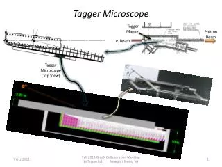
18. Alignment marks for defining the absolute position of the dipole magnets in the Tagger hall. Red - incoming beam (first magnet).Grey -2 GeV electrons.Blue - main beam exit from first magnet, and its extension to the second magnet.Green-7 GeV electrons.Magenta- Main beam exit.
19. Top view of alignment trajectories showing alignment points on both dipole pole shoes and the floor of tagger building.
The tagging spectrometer has been designed so that the complete system can be assembled on the support stands, at the manufacturer’s, where magnetic field and vacuum tests should be carried out. The vacuum tests should use a blanking flange on the tagger exit window. The spectrometer should then be taken apart, transported to Jlab and re-assembled. The magnetic field and vacuum tests should then be repeated firstly with the blanking flange and then with the proper window.