Download

1 / 11
110 likes | 258 Vues
LCLS Undulator Vacuum Chamber Design. Soon-Hong Lee Advanced Photon Source. CDR Vacuum Chamber Requirements. – Small Vertical Aperture (5 mm) and Thin wall (<0.5 mm) External Dimension: 6 mm OD x 3.42 m long (to fit within a 6.35 mm gap)

E N D
LCLS Undulator Vacuum Chamber Design Soon-Hong Lee Advanced Photon Source
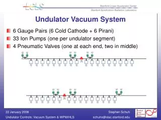
CDR Vacuum Chamber Requirements • – Small Vertical Aperture (5 mm) and Thin wall (<0.5 mm) • External Dimension: 6 mm OD x 3.42 m long (to fit within a 6.35 mm gap) • – Stable Geometry (No Vacuum deformation) • – High Conductivity Inner Surface • To minimize the electric resistive wake-field effects • – Low Surface roughness, Ra < 100 nm (h: ~100 nm, g: ~100 m) • To minimize the surface roughness wake-field effects • –High Melting Temperature • To survive during direct primary beam exposure • – Low Pressure and Low out-gassing rate (pumping only in undulator gap)
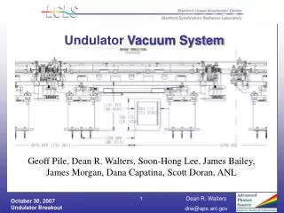
Vacuum Chamber Design I – Tube option • Concept I • Ni-Coating to mirror-finished SS 316L Tube and E.P. • Cu-coating and E.P. • E-Beam welding to SS horizontal support plate • TIG welding to strong-back vertical plate (or Clamping using fasteners) • Concept II • Electro-polishing of OFHC Cu Tube (As-drawn tube) • E-Beam tack welding to Cu plate • Brazing to SS horizontal support plate • TIG welding to strong-back vertical plate (or Clamping using fasteners)
Vacuum Chamber Design II – Box Option • Concept I • Machining 4-mm thick plates for beam aperture opening • Eletropolishing & Cu-Coating • E-Beam welding at both sides • E-Beam to SS horizontal plate • TIG welding to strong-back vertical plate (or Clamping using fasteners) • Concept II • Machining 8-mm thick plates for welding seats • Bend SS mirror-finished strip • Cu-coating to bended strip and E.P. • E-Beam welding to machined plate • TIG welding to strong-back vertical plate (or Clamping using fasteners)
Vacuum Chamber Development – Box option • Stress Analysis Aperture Maximum Displacement Maximum Stress Remarks 10 mm (H) x 5 mm (V) – Strip 0.52 m 8.15MPa Small aperture 6 mm 15 mm (H) x 5 mm (V) – Strip 5.86 m 41.7MPa Acceptable 25 mm 20 mm (H) x 5 mm (V) – Strip 19.2 m 106.4 MPa Out of criteria 20 mm (H) x 5 mm (V) aperture – Strip type Maximum Displacement: 19.2 m Maximum Stress: 106.4MPa 10 mm (H) x 5 mm (V) aperture- Strip type Maximum Displacement: 0.52 m Maximum Stress: 8.15MPa 10 mm (H) x 5 mm (V) – U-profile 2.22 m 35.8MPa Small aperture 12 mm (H) x 5 mm (V) – U-profile 3.72 m 42.1MPa Acceptable 15 mm(H) x 5 mm (V) – U-profile 9.40 m 84.2MPa Out of criteria 20 mm (H) x 5 mm (V) – U-profile 27.3 m 115.7MPa Out of criteria 6 mm 20 mm Criteria - Maximum Displacement < 10 m (?) - Maximum Stress < 69MPa (Safety factor w.r.t. yield stress: 3.0)
6 mm ~102.5 mm 15 mm (H) x 5 mm (V) aperture – Strip type Maximum Displacement: 7.60 m Maximum Stress: 59.9MPa Global Sensitivity Study Max. von Mises stress vs. horizontal aperture / Max. displacement vs. horizontal aperture 69 MPa 10 m 16.7 mm 16.5 mm • Global Sensitivity to horizontal aperture size
15 mm (H) x 5 mm (V) aperture – Strip with Strong-back Support Maximum Displacement: 18.88 m Maximum Stress: 48.3MPa Applied Loads & Constaints 3D –ProMechanica Model • Vacuum Chamber Analysis – Support structure
4 x E-Beam UHV Welding Leak Check I Prototype II Prototype I 8 mm 0.2 6 mm 0.1 Machining Both Surfaces Cu-Coated on mirror-finished SS 316L strips (1.5 mm thick) Cu-Cu E-beam Tack Welding Cu-SS Brazing SS316L OFHC Cu II • Vacuum Chamber Prototypes