Undulator Vacuum System
Undulator Vacuum System . Geoff Pile, Dean R. Walters, Soon-Hong Lee, James Bailey, James Morgan, Dana Capatina , Scott Doran, ANL. Undulator Vacuum System . Undulator Vacuum Chamber Support Status Production Schedule Bellows Module Testing: Combined Offset test and Surface Measurement

Undulator Vacuum System
E N D
Presentation Transcript
Undulator Vacuum System Geoff Pile, Dean R. Walters, Soon-Hong Lee, James Bailey, James Morgan, Dana Capatina, Scott Doran, ANL
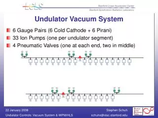
Undulator Vacuum System • Undulator Vacuum Chamber Support • Status • Production Schedule • Bellows Module • Testing: Combined Offset test and Surface Measurement • Production Plan • Quadrupole Spool • Design • Production Schedule • Long Break Spools • Standard Spool Design • Spools with Sector Valve • Production Plan • Beam Finder Wire • Status of Production • Modification to Chamber • Production Schedule • All Metal Chain Clamp Vacuum Seal • Testing Results
Undulator System Lattice L14-200000 SA-381-003-01 Undulator CELL L14-501000 SA-381-003-03 Support Mover System L14-401000 SA-381-006-24 Long Break Vacuum Spool L14406-111000 SA-381-014-70 Long Break Iso Vacuum Spool L14406-112000 SA-381-014-81 Long Break Diag. Vacuum Spool L14406-116000 SA-381-0XX-XX Girder Weldment L1430401-100396 SA-381-002-76 Pedestal Assembly L1430802-200000 SA-381-010-50 Girder Assembly L143-010000 SA-381-003-04 Girder Weldment L1430401-100396 SA-381-002-76 Undulator L143-112000 SA-381-001-35 BFW Assembly L14506-110000 SA-381-007-96 Quad Assembly L1430501-100394 SA-381-012-74 RFBPM Assembly L1450503-100000 SA-381-008-70 Vacuum Chamber L1440202-200000 SA-381-0XX-XX Bellows Module L14403-110000 SA-381-0XX-XX Ion Pump L14405-104000 SA-381-013-40 WPM-WLS L- MO-381-901-13 Control Assembly L142-100060 SA-381-011-28 BFW Support L14506-112000 SA-381-013-25 Quad Spool L14405-117000 SA-381-013-97 RFBPM Receiver L1450501-310000 SA-381-011-80 RFBPM Support L14505-104000 SA-381-014-39
Sub-Assemblies in the Undulator Vacuum System Ion Pump Bellows Module Undulator Magnet Beam Finder Wire Quadrupole Magnet Vacuum Chamber and Support RF Beam Position Monitor Wire Position Monitor Girder RF BPM Waveguide RF BPM Electronics
Tubing Support Structure • Production Status • Awarded to Walco Tool & Engineering (July, 2007). • Tubing material was changed to Aluminum 6061-T6 from Steel due to a magnetic material risk. (August, 2007) • Raw material was ordered in Sept. 2007 and was arrived at the vendor. (Oct. 18, 2007) • A first article is being fabricated to reduce the risk. • After rough machining, the tubing will be vibration stress relieved. • Two weeks lead-time from the painter. • One week for final machining and assembly.
Production Schedule • First Article Inspection • Support tubing will be inspected before starting the machining of remaining 36 assemblies. • Expect in the week of November 19th, 2007. • Within 2 weeks after inspection, APS will allow the vendor to cut the remaining materials. • Production completion • Lead time: 8 weeks after the first article inspection. • First Unit complete 12/10/2007 • Completion of remaining 36 assemblies: Week of Feb 4th, ’08. • Will be directly sent to SLAC from the vendor. • Shipping Carriers • Co-worked with Pak-Rite Ltd. to design the “Sure-Lok” shipping carrier. • 10 carriers were delivered to Walco (Sept. 07)
Bellows Module Design • Outer bellows assembly • EVAC flange with copper gasket and chain clamps • Removable tie rods for restraints to prevent damages • Travel Distance of a welded bellows (200-125-3-EE) • Internal pipe assembly • Inner pipe assembly with ID 10 mm x OD 12 mm x ~ 68 mm long pipe/tube • No finger assembly for electric conductivity • Gap in the Bellows will be of 7.8 mm +/- 6.5 mm • Pipe axis in the Bellows will be aligned to the Undulator within +/-100 m.
Surface finish measurement - Internal pipe • ID 10 mm pipes were honed for 2, 4, and 8 -inch Ra finish. • Roughness data after 2nd degree LMS fitting (polynomial data fitting line to line) show that either 2 -inch Ra or 4 -inch Ra honing process works fine. • RMS slope analysis shows that 2 -inch Ra is preferred and that 4 -inch Ra is marginal. Samples Sample 4Ra Sample 8Ra Sample 2Ra
Bellows Tests and Results • Original Tests (DCN 14403-0001). • Focused on internal sliding parts (RF and Spring Fingers). • ±2 mm X-Y offset with 0.5°angular offset x 2000 cycles. • Tests were completed. Internal parts met specification. • Sliding internal parts no longer used. New tests focused on maximum possible rotational and X-Y offset. • Flange rotation of ±~ 0.8° is possible with < 75 in-lb of torque. 2000 cycles were run. Leak check showed no leaks. • X-Y offset of ±10 mm is possible with ~ 10 lb of force. 2000 cycles were run. Leak check showed no leaks. • Further motion analysis showed rotational and X-Y offset may be simultaneously possible, but very unlikely. • Flange rotation of ~ 0.8° plus X-Y offset of ±9 mm is possible without permanently deforming the bellows. 50 cycles were run. Leak check showed no leaks.
Production Status • Outer bellows assembly • Edge-welded Bellows were received from Standard Bellows Company. • Welded flange (flange + adapter) • EVAC flange and its hardware were received from EVAC Inc. • Weld shrinkage of the flange sealing diameter must be compensated. • Drawings and SOW for production are complete. • Lead time 6 weeks for the 1st articles (2 ea), 8 weeks for the remaining balance. • Flange with weld-neck • Expect less shrinkage, but flange delivery for production will take 7 weeks ARO. • 4 custom-flanges with weld-neck will be weld tested. • Internal pipe assembly • Drawings and SOW for production are complete. • Internal surface finishing process is being tested. • Honing process was done. (honing oil - Perkins 284) • Vacuum cleaning-baking-RGA process is on progress. • Lead time 3 weeks for the 1st articles (2 ea), then 3 weeks for the remaining balance. • Production Schedule • First Articles complete on 1/31/2008 • 35 completed units on 3/25/2008 Weld Bead
Short Break Sub-Assembly Quadrupole Magnet RF BPM BFW Undulator Undulator Beam Girder Girder
Quad Spool Redesign and Production Schedule • New Requirements from Short Break Test • “Driveshaft” design with a small bellows on each end. • ±0.15° angular offset possible at each end. • 0.03” compression possible at both ends. • “Driveshaft” design allows X-Y offset > allowable from Quad. • Production Schedule • Design complete. All parts and fabrication on order. Small bellows delivery is driving the schedule. Bellows delivery scheduled for 11/7. • Ship bellows and flanges for first three units on 11/10 to AES for laser welding and post welding electro-polish. • Ship bellows to Alumiplate for interior aluminum plating. • First three units are scheduled for completion on 12/1. • If no design/QA problems are encountered, two additional production runs of 17 pieces each should be completed by 1/31.
BFW Assembly Mounted on Adjustable Support Electrical Connectors for Wire Signals Potentiometer Pneumatic Solenoid Valve Compression Spring Positioner Air Supply Shut Off Valve Precision Screw Card Position Monitor (Limit switches) Frame Housing Alignment Fiducials Pneumatic Cylinder Vacuum Pump Connector (2.75” Conflat Flange) Vacuum Chamber Connection Flange (NW-50 CeFix w/Clamp) Adjustable Mounting Support Beam Port
Status • Catalog Items– Delivery Complete • Machined Parts– Delivery Complete • Shaft Frame Weldment– First Article Delivered and Approved by ANL • BFW Vacuum Chamber– Contract Awarded. Delivery of 1st Lot within 5 weeks • Started Assembly of First Article at ANL • Assembly and Alignment Procedures— Completed Draft • Vacuum Test and Bake-out Procedures– Completed Draft • In Field Alignment Procedure– Conceptually Planned • Deliverables Drawing– Completed Draft
Significant Issues • Currently developing electrical interfaces with control group • Need to develop pneumatic interface • Need to develop wire signal interface • Need to develop protection cover strategy • Complete Assembly and Testing of the First Article • Modified beam tube to accommodate new BLM design • Modifed Ion Pump connection to allow space for BLM • Wire Card Installation Schedule for Completed BFW Assemblies w/ Supports to SLAC • Deliver 1st Lot (3) --- 12/12/07 • Deliver 2nd Lot (10) --- 1/14/08 • Deliver 3rd Lot (10) --- 2/11/08 • Deliver 4th Lot (14) --- 3/20/08
Short Break Test System 5 2 3 4 O-ring seal on hose to leak detector 1
Test Procedure • Initial tests (number #1-14) were conducted on individual seals to work out assembly technique. • Copper seals were used in tests #1-5 • Aluminum seals were used in tests #6-10 • Step #1 installed gasket at 60 in-lb • Step #2 Leak check • Step #3 increase torque 75 in-lb • Step #4 Leak check • Step #5 If it still leaks replace gasket and repeat steps #1-4 • Second round tests (number #15-27) • In this set of test all five gaskets were replaced using 75 in-lb of torque • In reporting the results only the leaks were noted. • Background of the leak detector was equal or lower that 1 X 10⁻¹⁰ mbar-lit/sec of helium • Leaks were defined as any reproducible meter deflection on any scale. • On test #18 the entire assembly was helium bagged for 10 minutes without any leak detector response. The results of the bagging of test #27 are shown in a later slide.
Transportation Test • Moved assembly onto hard wheel roller cart • Rolled around APS ring • Probe leak check • No leaks at 5 X 10-11 • Bagged the assembly • After 7 minutes a rise was noted • At 10 minutes leak rate rose to 5 X 10⁻¹⁰ • Loose tape seal around bag could be evidence of permeability of vacuum hose o-ring.
Induced Deflection Test & Aluminum Gaskets • Set-up • This is a test where a known leak tight assembly has a single component shifted 2 mm (.08”) and then re-leak checked. • Three test were performed • Each with a new gaskets to the component which in this case is the RFBPM • The assembly was leak tested • The component was moved 2 mm • Test #1 it was moved 2 mm in X direction • Test #2 it was moved 2 mm in Y direction • Test #3 it was moved -2 mm in Y direction • The assembly was leak checked again after moving • In all cases the assembly was leak free. • Transportation Test • At the end of Test #1 the assembly was rolled around the APS ring, greater than 1 km, and then leak checked one more time, no leaks. • ALUMINUM GASKETS • EVAC supplied replacement gaskets to replace the initial set • Tested 15 standard thickness gaskets, 2.17 mm, torqued to 39 in-lbs finding no leaks • Tested 5 extra thick gaskets, 2.36 mm, and were successful in 4 of 5. • These tests were conducted with Dicronite dry lubricant on the chains. • In further testing Armoloy XADC lubricated chains will be tried.