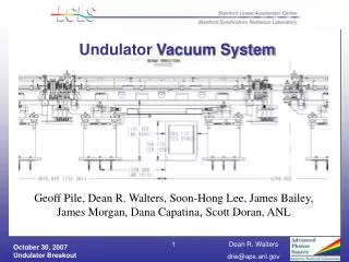
Undulator System Update
Undulator System Update. Facility Advisory Committee Review April 7 th and 8 th 2005 Stephen Milton Argonne National Laboratory Advanced Photon Source. Quick Overview Project Management and Administrative Items Organization Plan for the next 6 months FAC Responses

Undulator System Update
E N D
Presentation Transcript
Undulator System Update Facility Advisory Committee Review April 7th and 8th 2005 Stephen Milton Argonne National Laboratory Advanced Photon Source
Quick Overview Project Management and Administrative Items Organization Plan for the next 6 months FAC Responses Magnet Measurement Facility See Robert Ruland’s Talk in breakout session 1 and J. Sevilla’s breakout session 4. Physics Topics Magnet Support System Status Vacuum System Diagnostics Status Building Topics Controls Status System Integration Test Outline
Undulator Physics H.D. Nuhn Undulator Organization Undulator System System Manager S. Milton Chief Engineer/Deputy G. Pile CF Physics J. Welch Global Schedule and Integration R. Boyce PMCS Support P. Mast (AIM) F. Clark (ANL) SLAC Integration B. Youngman Controls System System Manager B. Dalesio System Layout TBD Magnetic Measurement R. Ruland Magnets and Supports M. White Vacuum and Diagnostics D. Walters Controls J. Stein
Faces • Geoff Pile • ANL LCLS Chief Engineer • Responsible for overall undulator system integration and will act in the role of my Deputy
Faces • Sushil Sharma • Fixed Supports Engineer • Will be responsible for the engineering and delivery of the undulator system fixed supports • Has already begun coordinating with Jim Welch
Faces • Horst Friedsam • ANL/SLAC Survey and Alignment Liason • Will coordinate with Robert Ruland to ensure all survey and alignment needs of the undulator system are met
New Roles • Undulator Integration Engineer (SLAC) • At SLAC Brad Youngman will oversee daily integration issue for the undulator system • Brad will report directly to Geoff Pile and myself • For administrative purposes Brad will also report to Mark, but ANL will have the final say on what Brad should be doing
New Roles • Controls • Bob Dalesio directs the overall LCLS Controls effort; therefore, • Josh Stein will work directly with Bob to ensure a robost integration of the overall LCLS controls system • For administrative purposes Josh will still report to me, but Bob will have final say in all controls issues
BPM System Build cold test prototype x-band beam detector Design receiver boards OTR Assemble and Test Prototype Wire Scanner Assemble and Test Prototype Support/Mover System Assemble and Test Prototype 1st Article Undulators Maybe receive 1st articles from assembly vendors Fixed Supports Finalize design and begin procurement for testing Vacuum Chamber Finalize testing of construction methods Start building prototype Project Management It never Ends 6 Month Look Ahead
FAC Responses • Cradle (Mover/Support) System Needs Attention • In addition to Emil Trakhtenberg an additional engineer, Jeff Collins, has been assigned to work on the Mover/Support System • All parts for the prototype have arrived and it will be assembled soon
FAC Responses • Trade-offs must be considered to decide whether longer girders can improve tolerance to ground motion • An engineer with experience in girder system (Sushil Sharma) has been assigned to fully develop the fixed support strategy and engineering • He is going over all trade-offs and he is responsible to make the decision, pending review, of the support system used
FAC Responses • The FAC recommends that, if the gap/period is changed, a new prototype is not necessary • We are not changing the gap or the period • Consider the use of feed-forward from temperature measurement to adjust the undulator horizontal position and control K • Although this has been discussed and the system is certainly capable of responding in such a fashion, we have not pursued it or tested it yet • Temperature readback of the undulator will be available
FAC Responses • The decision has been made to NOT hire a general contractor responsible for delivering complete undulators. The consequences of this decision (plans for control of final assembly) should be presented • The magnet design and engineering has been refined with ease and simplicity of construction in mind • A statement of work is being written and will include a complete description of the QA process to be followed • A QA person has been assigned to the project • A complete assembly procedure has been written and a video is being made of the assembly process • Two assembly vendors will be chosen • Assembly vendors are being prequalified • The 1st article from each of the two vendors will be thoroughly measured and tested before we will accept additional undulators • Frequent vendor visits will be made to the vendors to perform QA/QC checks and complete assembly travellers will be required for each undulator and component
Magnet Measurement Facility • SLAC Scope • ANL will act in both mentoring and consulting roles as the facility gets constructed and commissioned. • See Robert Ruland’s talk for more details • Undulator Measurement/Fiducialization/In-Situ Alignment : Breakout session 1 4:00pm
Break Lengths AC Conductivity What we did What we decided Radiation Calculations Preliminary Results Next Steps Alignment BPM Location Undulator Sections Wire idea Feedback Earth’s Field Correction Initial Basic Commission Steps Physics Issues
Undulator Break Lengths(Old Strategy) New Strategy • Characteristic Lengths • Length of Undulator Strongback (Segment):Lseg = 3.4 m • Distance for 113 x 2p Phase Slippage:L0 = (3.668 m)3.656 m • Distance for 2p Phase Slippage in Field Free Space: Linc = lu (1+K2/2) = 0.214 m • Standard Break Lengths Used • Use parameter n to characterize different phase length choicesLn = L0 -Lseg +(n-1)Linc • Use 2 Short Breaks Followed by 1 Long Break in n-Pattern 2 – 2 – 4 ([0.482 m – 0.482 m – 0.910 m])[0.470 m – 0.470 m – 0.898 m] • Fine Tuning of Initial Break Length • Suggested by N. Vinokurov based on Simulations by R. Dejus and N. Vinokurovusing Linear Simulation Code, RON • Small length increases for first 3 break lengths [0.045 m – 0.020 m – 0.005 m] • Total Undulator Length (from beginning of strongback 1 – end of strongback 33): Lund = (131.59 m) 131.52 m Taking from HD Nuhn’s FAC Talk
induced energy deviation for round chamber induced energy deviation for flat chamber AC Conductivity
AC Conductivity • What’s been done • Theory • Bane, Stupakov, Huang • Simulation • Fawley, Reiche, Emma • Measurements • Yu, Walters • What was decided • The beam sees Al • We use a flattened cross-section • We explore a variety of operating points during commissioning • There will be a much more complete description of what has been done supporting our decision during beakout session 1 of the FAC
Radiation Calculations • OTR Screens • We are concerned that the radiation produced by these screens when inserted into the beam could damage the undulator • Bingxin Yang produced a set of conditions and geometries that might be encountered and provided these to the SLAC radiation physicisit • Alberto Fassò chose the condition that would produce the most radiation and did simulations of it using his program FLUKA
Radiation Calculations The data in the literature seems to suggest that neutrons are most responsible for the degradation in performance of the permanent magnet blocks.
Radiation Calculations • Preliminary Results • Even with a 100 micron thick screen the simulation suggests that we could operate at 14 GeV with 1nC and at 120 Hz for 10 days before experiencing damaging demagetization • Real operations • We intend to use foils that are only a micron or two thick • We also plan to use the OTR screens only at low repetition rates (~10 Hz) and they will never be left in while we analyze data • However • Magnetic fields were not included in the FLUKA simulations • A field map will be given to Fassò along with other improvements in the geometry and operating conditions • The simulation will be done again with these improvements
Undulator Alignment • Question: How do you ensure that both ends of the undulator are on the desired line? • Beam-based alignment will be used to position the quadrupoles • The quadrupoles are “locked” to the end of the undulator with their magnetic centers aligned to the desired magnetic center of the undulator • The determines one end of the undulator • New idea • Use a wire at the other end of the undulator that has two positions: one out and one in to a fixed stop • The in position would be accurately aligned to the desired magnetic center of the undulator
Before any BBA or wire alignment performed After BBA: Quad, BPM and one end of the undulator aligned After Wire Alignment: Both ends of undulator aligned Undulator Alignment
Undulator Alignment • Wire Issues • How do you distinguish easily between the electron beam and the x-rays • The beam will create an easily seen radiation shower downstream or • You could first extract the undulators • Horizontal positioning is less critical than vertical • Would require a wire after each undulator • New idea • Needs some time to cook
BPM Location • Adjacent to the Quadrupole (SM) • If we believe the BPM absolutely then it could go on the other end and be used to align the downstream end of the undulator • No need to do this if we use the wire method • Advantages of being adjacent to the quadrupole • The quad locations are critical and the is no ambiguity with the BPM adjacent • Following BBA and following quad strength massaging one will have the offset (mechanical and electrical) of the BPM
Earth Magnetic Field Compensation Strategy • Earth Magnetic Field along Beam Trajectory in Undulator requires compensation. Estimated strength 0.43±0.06 Gauss : (0.18±0.03, -0.38±0.07,0.08±0.05) Gauss Based on Measurements by K. Hacker. (see LCLS-TN-05-4) • Compensation Strategy: • Position the Undulator on Magnetic Measurement Bench in same direction as in Undulator Tunnel • Compensate Earth Field Component in Undulator in Shimming Process • Scheduling Issues Taken from HD Nuhn’s FAC Presentation
Earth Magnetic Field CompensationAdjustable Shim Concept • Risk arises from the lack of precise knowledge of the earth field in the tunnel at the time of undulator segment tuning. • Considering mitigation strategy based on use of a small number of precisely adjustable shims along each undulator. • One extra shim per segment will reduce phase error by factor 4. • Shims will be installed before undulator tuning, but adjusted before undulator installation when field error has been determined. • Will not affect definition of magnetic center of undulator (Standard Undulator Axis, SUSA, [see PRD 1.4-001 4.7]) Also Taken from HD Nuhn’s FAC Presentation Undulator BPM Quad Undulator BPM Quad Quad Trajectory w/o Shim Shim Position Trajectory w/ Shim
Undulator Magnets Long Lead Procurements Strong team Lead by M. White Titanium Strongback Cost increase (Commodities Price) Magnet Poles Cost Decrease (Simplification) Magnet Blocks Magnet Assembly Supports Support Mover System Prototype being assembled Measurement equipment ordered Expect late May early June Testing CAM Mover system test Sliding stage measurements Fixed Supports Magnet and Support System Status
Und. Magnet: LLP, Ti Strongback • Status • Two Vendors Chosen • Cost higher than expected due to very rapid increase in cost of metal commodities over the last couple of years
Und. Magnet: LLP, Magnet Poles • Status • One Vendor Chosen • Based on cost • This vendor also had experience • Cost came is less than what we originally estimated • Due to simplification of the pole design • No ears
Und. Magnet: LLP, Magnet Blocks • Status • RFP Delayed • Spent additional time refining the sorting plan in the statement of work. • The successful vendor will be required to sort the magnet blocks prior to shipment to the assembly vendor • Do not expect the delay to impact the assembly schedule
Und. Magnet: Assembly • Plan to go with external assembly vendors • A lot of thought has gone into simplifying the assembly to the point that assembly can be done easily with simple training • How we will do it • A statement of work is being written and will include a complete description of the QA process to be followed • A QA person has been assigned to the project • A complete assembly procedure is being written and a video is being made of the assembly process • Assembly vendors are being prequalified • Two assembly vendors will be chosen • The 1st article from each of the two vendors will be thoroughly measured and tested before we will accept additional undulators • Frequent vendor visits will be made to perform QA/QC checks • Complete assembly travellers will be required for each undulator and component
Und. Magnet: Support/Mover System • Prototype parts in and assembly beginning • Testing expected in May/June • CAM, Sliding Mechanism, etc. E. Trahktenberg and J. Collins
Und. Magnet: Support/Mover System • Detail of Support/Mover System
Und. Magnet: Support/Mover System • CAM Mover system • Other system reconsidered • CAM mover still found to be the method of choice • Modifications made • Total CAM offset reduced to 1.5 mm • Better gearbox • Better bearings
Und. Magnet: Fixed Supports • Recent Change • ANL takes over scope of the fixed support system • Experienced engineer assigned to the fixed support • Sushil Sharma • In consultation with Jim Welch • Options being reconsidered • Past thinking has been to use granite supporting 3 undulators • Other ideas are also being explored
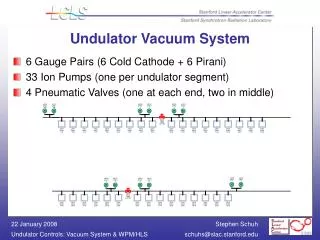
Vacuum System • Changes • Beam Sees Aluminum • Al on SS • Study of relative permeability • “Flat” cross-section Construction
Build chamber out of SS coated with Al What about the relative permeability? Curves on the right show the effect of both linear and nonlinear permeability on the undulator field = 1.1 15 mm x 5 mm chamber cross-section Expect SS relative permeabilities of less than 1.01 Looks OK but we will be doing more direct measurements to prove this is OK Waiting for accurate, calibrated permeability meter Vacuum System
Chamber Design • Start with SS Flat • Coat with Al • Bend to Desired U shape • Weld to Vacuum Strongback
Vacuum Status • Issues to address • SS permeability test • All samples in hand and parts in shops • ~1 Month samples ready for measurement • Check of welding, bending, and annealing effects • Survey Market for • Coating needs • Polishing needs • Fabrication
BPMs Location Plans OTR Screens Use Capabilities Based on APS Bunch Compressor Design Resolution Prototype Timeline Wire Scanners Use Rethinking need and use Undulator End Alignment Wire Intraundulator Xray Detectors Prototype plans Waiting for in-vacuum motion tests Vendor claims they will works Must pass APS tests first Other Charge Monitors Cerenkov Monitors “End-Of-Undulator” Diagnostics Diagnostics Status
Location At the Quad Plans Use X-Band RF BPM Internal Dimensions SLAC responsibility External ANL Responsibility Processing Electronics In-tunnel RF front end mixer Generic RF front end Capable for both cavity and stripline A/D Converter Team determined Diagnostics Status: BPM
Prototype Plans Build 4 cavities Machining done externally Brazing done at SLAC or externally To be determined Mount three on a rigid support and test with beam Beam tests to occur at FFTB/SPPS Closed in Mar. 06? Fall back location will be the APS PAR Bypass line PC Gun beam with bunch compression Timescale Will need 1 year Diagnostics Status: BPM B. Lill
Use Beam distribution measurement along the length of the undulator Can be used for emittance measurement as twiss parameter checks Features Commercial 2 inch lens tube, magnification adjustable with change of lens Integral tungsten shield Stepper driven remote focus Digital video camera, 30-fps at 1 MP, or 120 fps at VROI (250L), programmable gain. Manual iris control 5 to 10 micron resolution Based on APS Bunch Compressor OTR Success Prototype Parts on order Testing to occur in summer 05 Diagnostics: OTR Screens BX Yang
Based on SLAC design. Adapted for tighter space. Features Mounted on 6-inch flange On-axis drive mechanism in air Share space with other diagnostics (OTR and x-ray) Wire card to adapt SLAC design Test setup is being designed Actual use being re-examined Might switch to the simpler 2 state end alignment wire (see earlier description) Diagnostics: Wire Scanner J. Bailey, BX Yang
Diagnostics: OTR and WS testing • Measure wire scanner motion accuracy • Calibrate step size and cross check encoder outputs • Measure motion error in all three directions • Study motion error with different mounting orientation • Characterize OTR camera module • Calibrate pixel size • Measure optical resolution • Status • conceptual design in progress • In-Vacuum motors • Waiting for tests • Vendor claims good • Must pass APS standards
Undulator Hall and Buildings • Equipment Halls • Cable Length Runs • Temperature Control • Tight tolerances • 20± 0.2C • Needed for undulators (K value) • To minimize thermal expansion problems • Max (Min) Average power +50W/m (-50W/m) • Max power fluctuations 5W/m • For more details • Go to Welch talk at Breakout session 4 of the FAC
Undulator Hall and Buildings • Requirements/Desires • Keep heat sources out of the tunnel • Keep cable lengths to less than 150’ • Provide for convenient service and maintenance for all electronics Equipment Halls Additional Hole for future extension if needed Maximum Cable Length < 150’ 6 Undulators served per drill hole