HiCIAO Assembly Procedure: Comprehensive Guide for Fore-Optics and Vacuum Jacket Installation
This document outlines the assembly procedure for the HiCIAO system, focusing on the Fore-Optics and Vacuum Jacket (VJ) installation. Key components include the V-Truss Assembly, Common Path Filter Wheel Assembly, and the integration of the Closed Cycle Cooler. Detailed instructions guide the placement of shims and alignment of optical elements, ensuring optimal performance. Emphasis is placed on proper procedures to protect crucial components during assembly and maintenance. This guide supports the efficient installation of the HiCIAO system at the Subaru Telescope.

HiCIAO Assembly Procedure: Comprehensive Guide for Fore-Optics and Vacuum Jacket Installation
E N D
Presentation Transcript
HICIAO-Assembly-Procedure Prepared for HICIAO CDR Author: Vern Stahlberger Institute for Astronomy Date: 01-30-06
HICIAO + Fore-Optics Main access to inside of Cryostat is via VJ Top Cover: Weight ~10 kg HICIAO Fore-Optics; Mounts to AO-Bench Connectors are mounted on a large Sub-Plate to facilitate access to cables through the VJ 3 mm clearance between Fore-Optics and VJ
AO-Bench Interface Plate (Subaru-design); to match up with holes on dowel pins to this face Fore-Optics is decoupled from Vacuum Jacket! 3mm Gap between HICIAO VJ and Fore-Optics Assembly
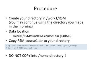
Starting point for HICIAO Assembly Sequence V-Truss Assembly (Qty=4) VJ Bottom Plate
Note: Lip on the Optics Bench for Light-Seal V-Truss Light Shield Brass Slides Qty=3 Optics Bench Cutouts for Detector Assembly • Brass Slides permit slight adjustments along the optical axis • For Assembly, use shims in places indicated Place Shims here
Shim Location Common Path Filter Wheel Assembly (CPFW) Install Light-Tube-1 to CPFW Use .344 inch thick shim to locate CPFW to nominal position; place shim between Filter cover and inside of Optics Bench
Pupil Wheel Assembly (PW) Slide PW up flush against Light-Tube-1 Light-Tube-1 Install Light-Tube-2
Add Detector Assembly: It must be installed prior to the Differential Path Filter Wheel (DPFW) Detector Assembly Prepare ASIC Flex Ribbon Cable as shown
Light-Tube-2 Tongue Light Shield Bottom out against Light-Tube-2 prior to inserting DFPW To keep the Optics Path light tight, a Tongue & Groove design interface is used for the 2 marked parts; the Tongue Light Shield must be inserted before the DPFW
Filter Wheel Case Once DPFW is installed, bottom out Tongue Light Shield on Filter Wheel Case and secure with 2 screws Tongue Light Shield DPFW
Assembly: Closed Cycle Cooler and 1st Stage Strap to Vacuum Jacket
9x ¼-20 Socket Head Caps with Washer 1st Stage Strap (compliant) 1st Stage Strap is composed of .12mm thick Copper Foils and bent into the configuration shown to cancel out vibrations from the 1050 CTI Cold Head
Clamp type design to secure the 1st Stage Strap to the Optics Bench; screws are located on the inside of the Optics Bench (previous slide)
VJ Lower Body Hex Socket Head M6 x 25 25 Required Evacuation Valve; Rotates through 360 Deg Connectors and Connector Sub-Plates should be installed AFTER the VJ Lower Body has been bolted in place!
Prepare Radiation Shield as shown in this slide; add to Assembly S.H.C.Vented 6-32 x 5/8 32 Required
Radiation Shield without Shield Top Plate Note: This assembly state should be used to wire up the instrument
CTI Cold Finger will slide through the inside of the Getter Shield Getter Shield attached to Radiation Shield Tube 1st Stage Strap
Vibration Isolation Mount Closed Cycle Cooler Assembly 1st Strap Access Cover 2nd Stage Getter Assembly CTI 1050 Cold Head Safety Finger Qty3 Cold Wire to Detector CCC Mount Flange Prior to Vacuum, the CCC Cold Head is loose. After Vacuum is applied Cold Head is compressing the 2 Isolation Rings (Rubber); 3 Safety Fingers limit the motion of the Cold Head with no Vacuum
1050 CTI Cooler assembled to Vacuum Jacket Use these Screws to limit movement of CCC Cold Head when not under Vacuum; 3 Places Access Hole in CCC Mount Flange; used to bolt 1st Stage Strap to CCC Cold Finger
Access Covers to Filter/Lenses Hall Sensor Mount This and next slide show state of disassembly necessary to perform maintenance and change filters/sensors/lenses etc.
HICIAO Installation on NASMYTH • After PDR, Fore-Optics and Vacuum Jacket became 2 independently mounted assemblies • Wollaston Prism is close to Vacuum Jacket for optical performance reasons • Must protect Wollaston Prism from possible collision with Vacuum Jacket upon installation • Next slides discuss new design for mounting procedure of Fore-Optics and Vacuum Jacket on Nasmyth Floor
HiCIAO Nasmyth InterfacePreliminary Proposal Hideki Takami, Michael Eldred February 8, 2006
Instrument Layout IRCS at AO focus CISCO IRCS Laser Room AO
Instrument Layout IRCS and AO at docking station IRCS Laser Room AO
Instrument Layout HiCIAO at AO focus 4 fixed points for IRCS HiCIAO IRCS Laser Room AO
Instrument Layout IRCS at AO focus HiCIAO IRCS Laser Room AO
Brief Overview of Installation Procedure1) Install the Fore-Optics Assembly to the AO-Interface Plate mounted to AO-Bench2) Transport HICIAO VJ and Interface Frame to the site either by Crane of Rail ( Subaru’s decision)3) HICIAO VJ must be in the retracted position!4) Move HICIAO to observing position using crankThe following slides will explain in detail the procedure, including initial setup and alignment.
Interlocking Pin: Qty=2 Side Adjust Bracket Qty=4 VJ Bottom Plate Opt-Axis Adjust Rail Qty=2 Foot Focus Adjustment Qty=4 Z-Shim Qty=4
Comments on previous slide: • The Side Adjust Brackets are used for the initial alignment; once set, they will remain locked. • The Z-Shim likewise will be adjusted during initial setup; once the optical axes has been aligned, no further adjustments are needed; at this point the Opt-Axis Adjust Rails are secured with bolts through the Z-Shims into the Interface Structure (Bolts not shown) • The horizontal slots in the Foot Focus Adjustment are used for fine-tuning the focus direction of the HICIAO instrument. • ONCE THE INITIAL SETUP IS COMPLETED, THE HICIAO INSTRUMENT CAN SIMPLY BE RETRACTED BEFORE AND AFTER INSTALLATION BY MEANS OF THE CRANK ON THE RIGHT. • The Interlocking Pins require the Vacuum Jacket to be moved horizontally away from the Fore-Optics for the first inch or so. • There is also a design feature to allow for precise, repeat positioning of the Vacuum Jacket w.r.t. Interface Structure. This is shown in the next slides.
Interlocking Pin Qty=2 Press fitted to VJ Bottom Plate VJ Bottom Plate omitted Hand Crank Register Pin Qty=2; Attached to VJ Front End Stop Plate
Repositioning Hardware required on Vacuum Jacket Register Pin; bolted to VJ Bottom Plate; electrically insulated from VJ Interlocking Pin
INITIAL SETUP: (with VJ sitting on Target Assemblies) • Adjust Front End Stop Plate such that the optical beam coming from the AO is parallel to the optical axis of Cryostat. Front End Stop Plate has rotational adjustment around a vector perpendicular to the Nasmyth Floor. • Adjust the Z-Shims to align the optical axis of the AO beam and Cryostat in the direction perpendicular to the Nasmyth Floor. ( Step 1 and Step 2 can be reversed) • Move the Cryostat sidewise using the Side Adjust Brackets until the optical axis of the AO and the Cryostat coincide. Secure bolts that fasten the Opt-Axis Adjust Rails to the Instrument Frame. • Fine tune any Focus errors by using the horizontal slots in the Foot Focus Adjustment. • a) The Register Pins are bolted to the bottom of the VJ Bottom Plate (previous slide) • Both the Register Pins and Front End Stop Plate have hardened surfaces where they match. The match on the near side is between the Register Pin and a V-Groove in the Front End Stop Plate, at the far side between the Register Pin and a rectangular slot (see next slide). This will insure accurate repeat positioning in x and y. • c) Interlocking Pins and corresponding holes in the Fore-Optics Structure have enough clearance between them to never touch. The Interlocking Pins serve as a safety feature in that the cryostat cannot be moved in any other direction than horizontally away from the Fore-Optics Assembly for the first inch.
Arrangement assures repeat positioning of VJ on Interface Structure Rectangular Slot V-Groove Interlock Pin Qty=2
HICIAO mounted to Instrument Structure HICIAO will either use its own Target Assemblies or use IRCS Target Assemblies. (no final decision yet) Target Assembly Qty=4
CRYO-MECHANISMS HICIAO uses 4 CRYO-Mechanisms Common Path Filter Wheel (CPFW) Pupil Wheel (PW) Differential Path Filter Wheel (DPFW) Detector Focus Mechanism Except for the Wheels, the CPFW, PW and DPFW are identical in design
Common Path Filter Wheel Front Back Dowels lineup unit perpendicular to Optics Bench Mounting surface Cover shown partially transparent For more Details: See PDR Document 3.2.2.3.6
Filter Wheel Case Holder Mechanism Registration: Brass Slides permits parallel, limited translation along the optical axis Slotted Holes; allow limited adjustment along the optical axis
Filter Wheel Cover removed Magnets in Wheel Detent Spring Detent Cam & Driver Assembly Hall Sensor Geneva Wheel 12 positions Filter Cell
Filter Access Cover; held in place with leaf spring PHYTRON CRYO-Motor Hall Sensor Gear Train Ratio 8:1 Bearing Mount
Detector Focus Mechanism Maximum Travel Range: +/- 8 mm Resolution: 5 micron Drive System: Linear Ball Bushings with Ball Screw Drive Encoding: Hall Sensor & Magnet
Detector and Detector Focus Stage Resolution: 5 micron Drive: Linear Ball Slides w/Ball Screw Drive Front View Back View
ASIC (Schematic only) Hall Sensor Substrate Hall Sensor Substrate Cold Feed-Through with G-10 Disk thermal insulation Ball Screw Drive 1mm Pitch THK Linear Ball Slides Flex Connection
PHYTRON CRYO-Motor G-10 Isolation Tabs Qty=4 Ball-Screw Bracket